Calculating the reaction forces and bending moment distributions in a simply supported beam.
This is the second in a series of articles diving into the various calculations used in civil and mechanical engineering, such as our article on calculating stress. For this one, we’re going to look at reaction forces in a simply supported beam.
What is a beam?
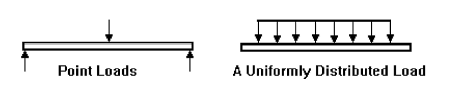
Before we can understand what reaction forces are in a beam, we need to be clear on what a beam actually is. A beam is a structure that is loaded sideways, or transversely. The loads can be point loads or Uniformly Distributed Loads (UDL). The image below shows the difference between them:
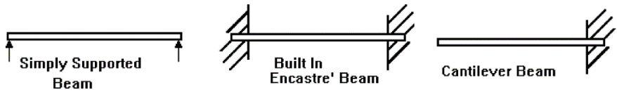
Beams can be simply supported or built in:
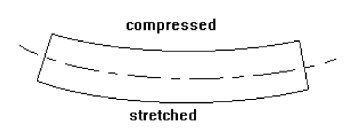
Transverse loading causes bending, which is a severe form of stressing a structure. The bent beam is stretched on one side (in tension) and compressed on the other:
So now we know what beams are, we can look at how we can analyse the stress they’re subject to when loaded.
Calculating Reaction Forces
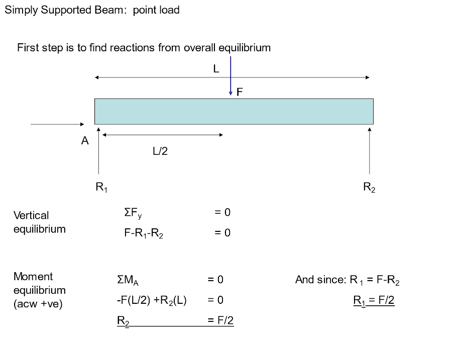
Imagine a 3m beam is simply supported at each end, then loaded in the centre with a point load of 2kN. We’re going to calculate the reaction forces at each end of the beam.
As the beam is in equilibrium (forces are balanced and there is no acceleration, then:
F=ma=0
M=0
Therefore, resolving vertically: R1 + R2 – 2 = 0
Taking Moments about left hand end (acw +ve): (-2)(1.5) + 3R2 = 0. Solving this equation gives us: 3R2 = 3 and hence R2 = 1kN which from the first equation implies that R1 = 1kN also.
Now, we could have used our intuition to figure this out, as when the load is in the centre then the reaction forces will be half of the load at each end of the beam. However, it’s always worth confirming using the correct calculations.
This can be summarised below:
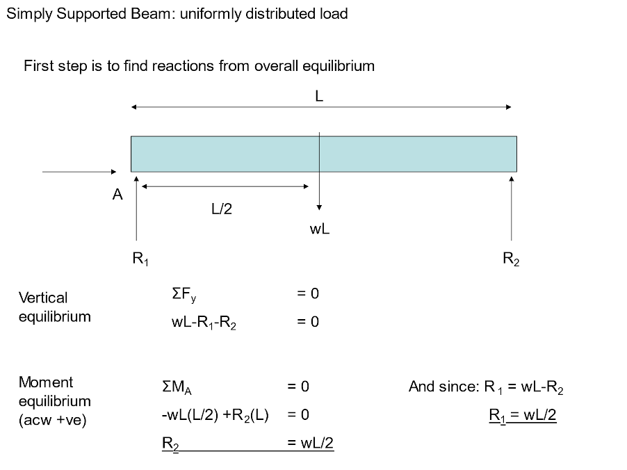
Uniformly Distributed Loads
For the case of a uniformly distributed load (UDL) the equations can be modified slightly.
Determine Shear Force and Bending Moment Distributions
Look at the simply supported beam below
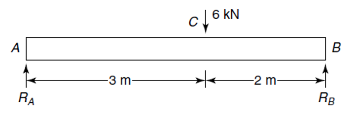
After we have found the reaction forces, we then determine the shear force and bending moment distributions along the length of the beam. These are known as internal forces, as opposed to the external forces that are applied to the beam, i.e. they can be thought of as existing inside of the beam.
To determine these internal forces and moments, we must use our imagination and take an imaginary ‘cut’ at some arbitrary point along the beam (position x) between the first two forces from the left, as shown below.
We also add the value of the internal shear force at position x, qx, and the internal bending moment at position x, Mx, using the convention as shown:
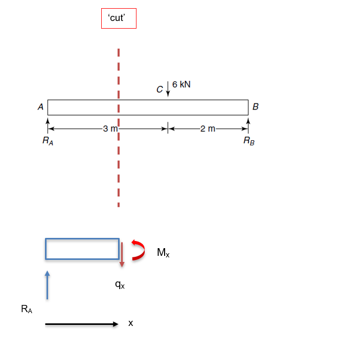
The section of the beam that is now ‘cut’ is also considered to be in equilibrium, and so we apply the equations of resolving forces and moments in the same way as we did previously for the whole beam when we were calculating the reaction forces:
qx=RA=2.4kN
Notice that we chose an arbitrary position along the length of the beam between points A and C and so this tells us that the shear force, qx, in between these two points has a constant value of 2.4kN.
Now take moments about the cut:
Mx-RAx=0Mx=RAx kNm
This is the equation that tells us how the bending moment varies as a function of x between points A and C.
Now we need to take another ‘cut’ as shown below:
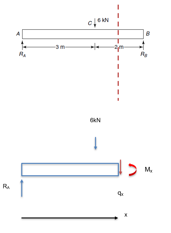
Now take moments about the cut:
Mx-RAx+6x-3=0
Mx=RAx-6x-3 kNm
Mx=2.4x-6x-3
Let’s summarise our results:
| Position | A to C | A to B |
| Shear Force, qx | qx=2.4kN | qx=-3.6kN |
| Bending Moment, Mx | Mx=2.4x kNm | Mx=2.4x-6x-3 kNm |
We can now use this information to produce shear force and bending moment diagrams, as shown below:
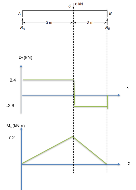
The maximum value of the bending moment is of particular interest to us, as it is used in the next step to calculate the maximum bending stress.
From the above it can be seen that the maximum bending moment happens when x = 3m and you will see that we can use either of the above equations for the bending moment as they will both give the same value at this point.
Mx=2.4x =2.43=7.2 kNm
Or
Mx=2.4x-6x-3=2.43-63-3=2.43=7.2 kNm
Note: you can use the above fact as a check that you have found the correct equations. If you do not get the same values, then you have not formulated the equations correctly!
Stay tuned for more articles in the series so you can learn even more calculations to help you in your civil or mechanical engineering career.
Interested in our courses?
Interested in civil or mechanical engineering? Find out more about all the civil engineering courses we have available by clicking here, and the mechanical engineering courses by clicking here.
Diploma in Mechanical Engineering
Diploma in Mechanical Technology
Diploma in Sustainable Construction
Diploma in Structural Engineering
Diploma in Building and Construction Engineering
Higher International Certificate in Civil Engineering
Higher International Diploma in Civil Engineering
Higher International Diploma in Mechanical Engineering
Higher International Certificate in Mechanical Engineering
Alternatively, you can view all our online engineering courses here.
Recent Posts
Civil Engineering Courses and Diplomas: Topics, Skills and Career Routes
Civil Engineering Courses and Diplomas: Topics, Skills and Career Routes Introduction Civil engineering is the backbone of modern society. From roads and bridges to skyscrapers and water systems, civil engineers design, build, and maintain the infrastructure that keeps the world running. If you’re considering a civil engineering course or diploma, understanding what it covers is […]
What Is a Diploma in Engineering? Courses, Levels and Career Routes Explained
What Is a Diploma in Engineering? Courses, Levels and Career Routes Explained Introduction Engineering shapes the world around us, from the buildings we live in to the technology we use every day. But for many aspiring engineers, the biggest question is not whether to pursue engineering, but how to start. Traditional university degrees are not […]
Engineering Courses: How to Choose the Right Route for Your Career
Engineering Courses: How to Choose the Right Route for Your Career Introduction Choosing an engineering course can feel like standing at the beginning of several different roads, each leading towards a different kind of future. One route may lead into mechanical systems and manufacturing. Another may lead towards aircraft, infrastructure, electronics, computing, renewable energy or […]