Determine the effects of torsional loads on shafts.
We’re going to continue our series of articles on the calculations used in civil and mechanical engineering by diving into torsional loads on shafts and their effects.
The image below shows a motor supplied with power which causes a shaft to rotate. The rotating shaft causes the pulley to rotate and left a load, which gains energy. The power input to the motor has been transmitted to the load by the shaft. But how does this work?
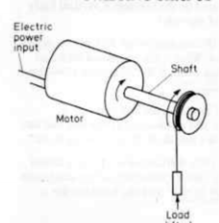
If a strip of rubber is held with an end in each hand and twisted, a twisting action is seen, which transmits along the rubber. The twisting action starts at one end of the rubber and is transmitted along it to the other hand. The power is transmitted along the rubber by the twisting.
The shaft of the motor behaves in the same way. The motor exerts a twisting action on one end of the shaft, and this is transmitted along the shaft, resulting in the twisting action being communicated to the pulley wheel. This twisting action is called torsion.
The diagram below shows a shaft held rigidly at one end. No torque is applied to the shaft on the left, and the bar is a straight line, parallel to the axis of the bar.
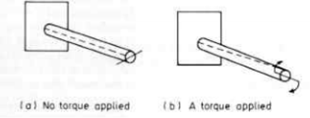
However, when a torque is applied, as we can see on the right-hand side of the diagram, the bar twists and becomes distorted. The further down the bar from the end where the torque is applied, the less movement of the mark from its initial position. The twisting action has been transmitted down the bar, and torque has been experienced by different sections of the bar.
Torsional Stresses
Torsional stresses develop in shafts when a torsional load is applied. Typical applications of torsional loads and stresses can be found in many aspects of engineering, wherever we find shafts to transmit power. Some of these examples are:
- Gas (air) enters on the left and is compressed (pressure increases) in the compressor.
- The gas then enters the combustion chamber, where its energy is increased due to the addition of fuel and the combustion process.
- The gas then flows through the turbine, where some energy is extracted from the now high energy flow field, and this turbine is connected to the compressor via a shaft running through the centre of the engine.
- The remainder of the gas exits via the nozzle.
The shaft is therefore subject to high torsional loads and stresses.
Another example can be seen below in this diagram of a marine propellor shaft:
The Calculations
Let’s check out an example:

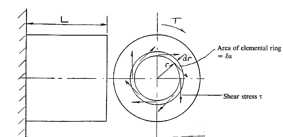
By considering the shear strain produced by twisting the shaft it can be shown that

By considering the torque T (twisting moment) acting on the shaft is can be shown that

By combining these two equations we can state the following:

T = Torque
J = Polar second moment of area
= Shear stress at radius r
G = Modulus of Rigidity (Shear Modulus)
= Angle of twist over length L
For a solid shaft, with a radius of R (and diameter D):

For a hollow shaft, with a radius of R (and diameter D):

For a thin tube, t<<R, where t = thickness:

It is also useful to know the following relationship between the power of a shaft, P and the torque, T:
P=Tω
where is the angular velocity (rad/s).
It’s worth noting that angular velocity is commonly quoted in RPM (revolutions per minute) or Hertz or Hz. (revolutions per second). However, you should note that the SI units of angular velocity are radians per second (rad/s).
Let us look at how to convert between these units. RPM60=revolutions per second=1 Hz
ω=2πf Where f = angular velocity in Hz.
Therefore: RPM60x2π=rad/s
Keep an eye out for more articles on more exciting calculations that will help you throughout your career.
Interested in our courses?
Interested in civil or mechanical engineering? Find out more about all the civil engineering courses we have available by clicking here, and the mechanical engineering courses by clicking here.
Diploma in Mechanical Engineering
Diploma in Mechanical Technology
Diploma in Sustainable Construction
Diploma in Structural Engineering
Diploma in Building and Construction Engineering
Higher International Certificate in Civil Engineering
Higher International Diploma in Civil Engineering
Higher International Diploma in Mechanical Engineering
Higher International Certificate in Mechanical Engineering
Alternatively, you can view all our online engineering courses here.
Recent Posts
Civil Engineering Courses and Diplomas: Topics, Skills and Career Routes
Civil Engineering Courses and Diplomas: Topics, Skills and Career Routes Introduction Civil engineering is the backbone of modern society. From roads and bridges to skyscrapers and water systems, civil engineers design, build, and maintain the infrastructure that keeps the world running. If you’re considering a civil engineering course or diploma, understanding what it covers is […]
What Is a Diploma in Engineering? Courses, Levels and Career Routes Explained
What Is a Diploma in Engineering? Courses, Levels and Career Routes Explained Introduction Engineering shapes the world around us, from the buildings we live in to the technology we use every day. But for many aspiring engineers, the biggest question is not whether to pursue engineering, but how to start. Traditional university degrees are not […]
Engineering Courses: How to Choose the Right Route for Your Career
Engineering Courses: How to Choose the Right Route for Your Career Introduction Choosing an engineering course can feel like standing at the beginning of several different roads, each leading towards a different kind of future. One route may lead into mechanical systems and manufacturing. Another may lead towards aircraft, infrastructure, electronics, computing, renewable energy or […]