What is joining and why is it important in Engineering?
Joining can be considered the third primary manufacturing process, it is an important step in the manufacture of parts with complex shapes, or unusual geometric features.
Using the primary processes of casting and forming, it may not be technically or economically feasible to create parts with such complex shapes. In these cases, making small simple parts and joining them together is the best possible way.
Joining consists of a large number of processes used to assemble two or more parts together, irrespective of their composition, properties, features, shapes, etc.
It is important to note that further secondary processing may still be used after joining to complete the part manufacture.
The most common joining processes used in the engineering industry are:
- Fasteners (threaded fasteners, pins, rivets etc)
- Adhesive bonding
- Resin bonding
- Soldering
- Brazing
- Welding
We are going to focus on welding.
Types of Weld

Basic Weld Strengths
Knowing the strength of joints is critical for engineering structures.
In this blog, we will cover the basic calculations for weld strength in two types of joints. The tensile strength of a butt joint, and the shear loading of a fillet weld.

.
Tensile strength of a butt joint

For a successful weld of a butt joint, there is a requirement that the tensile strength of the weld material is greater than that of the base material.
That is:
σw > σb
where σw is the tensile strength of the weld material,and σw is the tensile strength of the base material.
However, in most engineering situations, you would want to account for a safety factor, which allows for any imperfections in the weld quality. If we call this safety factor Fs, then in practise:
σw ≥ Fs x σb
As long as this relationship is maintained, then the weld will hold.
Shear loading of a fillet weld
If the load applied is not perfectly perpendicular to the fillet weld (as per above) then the weld is in shear, and its load carrying ability is reduced.
For this reason, when designing welds we always assume that the weld will be loaded in shear as seen below.

Assume the load is applied at point A, pulling out of the page.
So drawn from above

In this case the applied load is parallel to the welds. The forces are pulling the two components being joined in opposite directions, which places the welds under shear.
When a weld is in shear we can no longer use the tensile strength of the filler metal to determine the strength of the weld. So we introduce a further safety factor. It is common industry practice that the requirement for the minimum tensile strength of the filler metal be multiplied by 0.30 to obtain the allowable shear stress on the weld.
That is, only 30% of the allowable tensile load can be used.
τallowable = F/A
Where τallowable is the allowable shear strength (i.e.σw x 0.3), F is the force applied, A is the effective area of the weld.
The effective area of a weld is calculated by multiplying the length of the weld times the throat of the weld. For design purposes we use the theoretical throat as shown below.
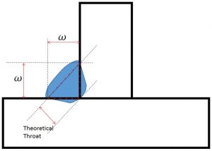
In the above diagram, “w” is the fillet weld size. Using trigonometry you can determine that the theoretical throat is calculated by multiplying “w” times the cosine of 45. For quick reference (cosine of 45˚= 0.707), therefore for all fillet welds with both height and weight being of the same size (w), the theoretical throat will be 0.707 x “w”.
If the weld is 20cm in length then the effective area will be 20cm x 0.707 x “w” .
Interested in our engineering courses?
We have over 70 courses across all major engineering disciplines, including, mechanical, electrical and electronic, civil, aerospace, industrial, computer and general engineering. Visit our course catalogue for a complete list of fully accredited engineering programmes.
A small selection of short courses …
Level 6 Courses
International Graduate Diploma in Mechanical Engineering
Level 5 Courses
Higher International Diploma in Industrial Engineering
Higher International Diploma in Mechanical Engineering
Level 4 Courses
Higher International Certificate in Industrial Engineering
Higher International Certificate in Mechanical Engineering
Alternatively, you can view all our online engineering courses here.
Recent Posts
Understanding Key Performance Indicators in Manufacturing
Understanding Key Performance Indicators in Manufacturing Introduction Key Performance Indicators (KPIs), or sometimes written as Key Performance Measures, are some of the key ‘metrics’ that are used to measure the performance of an industrial system. A good KPI for a manufacturing system should be SMART, that is: Specific – It should measure a specific output […]
How Aircraft Structures Evolved: From Fragile Flyers to Engineering Masterpieces
How Aircraft Structures Evolved: From Fragile Flyers to Engineering Masterpieces Introduction As with all other aspects involved with an aircraft, the structural design and layout has changed markedly over the history of flight, in line with technological advances and new discoveries. This section will highlight some of the more substantial developments made during the history […]
Why Lean Manufacturing Matters: Principles of waste
Why Lean Manufacturing Matters: Principles of waste Introduction Lean manufacturing isn’t just a toolkit for improving efficiency, it’s a mindset that reshapes how organisations think about value. At its core, lean focuses on delivering exactly what the customer needs, when they need it, with as little waste as possible. In an increasingly competitive and resource-conscious […]