Essential Cooling and Protection Devices: How They Work and Why They Matter
Introduction
Generators produce a significant amount of heat and electrical stress during operation, which can affect performance and lifespan if not properly managed. That’s where cooling and protection devices come in. These essential systems, including fans, radiators, circuit breakers, and relays, work together to maintain safe temperatures and prevent damage from overloads or faults. In this article, we’ll explore how these mechanisms function and why they’re critical to keeping generators reliable and efficient.
Maintenance of Electric Generator
Proper maintenance of an electric generator is essential for ensuring its longevity, reliability, and safe operation.
Maintenance Schedule Summary
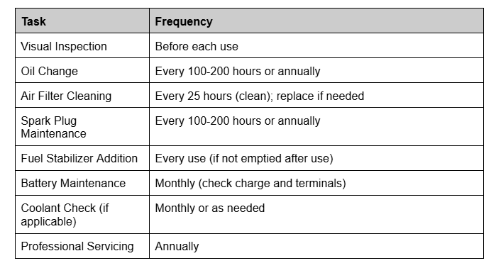
Tips for Long-Term Reliability
- Follow the manufacturer’s maintenance manual for model-specific guidelines.
- Keep detailed records of maintenance and servicing.
- Use high-quality parts and accessories to avoid premature wear.
Cooling methods
Generators employ various cooling methods to prevent overheating and ensure optimal performance. Here are the most common generator cooling methods:
Air Cooling
Air is used to cool the generator by directing airflow over the engine and components. A fan or fins on the engine helps dissipate heat. Used in small and portable generators. Simple design, lightweight, and low maintenance, but limited cooling capacity, making it unsuitable for large generators
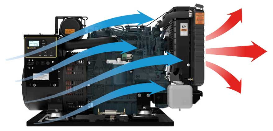
Open-Ventilated Systems
In an open-ventilated cooling system, the process begins with the generator drawing in fresh, cool air from the surrounding atmosphere. This air, often propelled by built-in fans or natural airflow, serves as the primary medium for heat absorption. As the generator operates, its components, such as the engine and alternator, generate significant heat. The cool air flows over these components, absorbing the heat and ensuring the generator’s internal temperature remains within safe operating limits.
Once the air has absorbed the heat, it becomes significantly warmer. To prevent overheating and recirculation of this hot air, the system directs it out through an exhaust or ventilation pathway. This expulsion of hot air back into the atmosphere ensures a continuous cycle of fresh, cool air entering the system.
This straightforward process makes open-ventilated systems highly efficient for small to medium-sized generators. The simplicity of the design reduces maintenance needs and eliminates the complexity of liquid coolants or additional cooling mechanisms. However, the system’s effectiveness depends heavily on the ambient environment. In cooler climates or well-ventilated spaces, it works seamlessly. Conversely, in hot or confined areas, the cooling efficiency can decrease, as the intake air is already warm or airflow is restricted.
Overall, the open-ventilated cooling system is a reliable and cost-effective solution for generators that don’t produce excessive heat or operate in challenging conditions, making it a practical choice for many small-scale and portable applications.
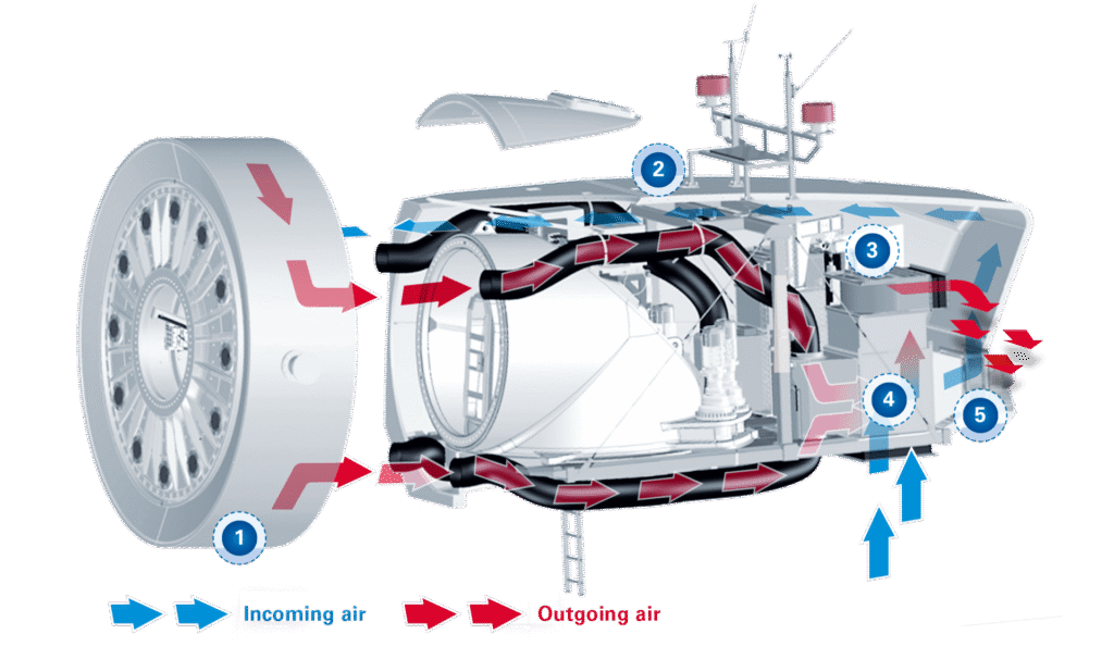
Enclosed Ventilated Systems
An enclosed ventilation system is a critical component for managing heat and airflow in generators housed within a confined or enclosed space, such as a room or protective casing. The system begins by drawing in fresh air through strategically placed intake vents or ducts. This cool air circulates within the enclosure, absorbing heat from essential components like the engine and alternator. To maintain optimal performance, the heated air is then expelled efficiently through exhaust vents or ducts, often assisted by fans or blowers.
This controlled environment provides multiple benefits. It protects the generator from external elements like dust, rain, or extreme temperatures, ensuring longevity and reliability. Many enclosed systems also incorporate soundproofing materials, reducing noise pollution, a key advantage in residential or urban settings. While effective, these systems require careful design to avoid overheating, proper maintenance to prevent blockages, and an initial investment that includes enclosures, ventilation equipment, and temperature monitoring systems. Ideal for industrial, residential, and environmentally challenging locations, enclosed ventilation systems offer enhanced cooling, noise reduction, and environmental protection, making them indispensable for generators in demanding settings.
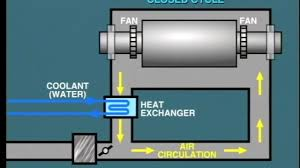
Liquid Cooling
A liquid (usually water, coolant, or a mix) circulates through the engine, absorbing heat. The heated liquid is then cooled in a radiator or heat exchanger.
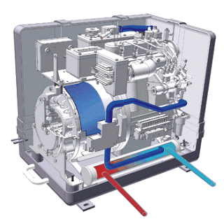
Found in larger generators, typically 15 kW and above. Efficient cooling for high-powered systems. Operates more quietly than air-cooled systems, but more complex and requires regular maintenance (e.g., checking coolant levels, flushing the system).
Oil Cooling
Oil circulates around the engine to absorb heat, then passes through a cooler to dissipate the heat. Common in some specialized industrial generators and engines. Durable and effective for long-term use in specific environments, but requires consistent oil checks and replacement.
Hydrogen Cooling
Hydrogen gas, which has high thermal conductivity, circulates around the generator to absorb and dissipate heat.
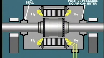
Used in very large generators, such as those in power plants. Highly efficient, reduces energy loss, and supports compact generator design, but requires specialized equipment to handle hydrogen safely.
Combined Air and Liquid Cooling
Combines air cooling for some components and liquid cooling for the engine. Found in mid-sized generators where liquid cooling alone may not be sufficient. Balances efficiency and cost, but more complex than single-method cooling systems.
Evaporative Cooling
Water or a coolant is sprayed onto hot components, and the evaporation process absorbs the heat. Primarily used in industrial and large-scale generators. Highly efficient for extremely high-power applications, but requires a consistent water supply and maintenance of evaporation systems.
Heat Exchangers
Heat from the engine coolant is transferred to a secondary fluid (often air or water) in a heat exchanger, which dissipates the heat. Common in marine and industrial generators. Effective in environments where direct air cooling isn’t possible, but Increases system complexity.
When selecting a generator, consider its cooling method based on your power needs, operating environment, and maintenance capacity. Proper cooling ensures longevity and efficiency for your generator.
Why is cooling essential ?
Cooling in a generator is essential to maintain optimal performance, prevent damage, and ensure safety during operation. Generators produce significant amounts of heat due to the combustion process in the engine and electrical resistance in the alternator. Here are the primary reasons why cooling is necessary:
Prevent Overheating: Engines and alternators generate heat during power production. Without cooling, components can overheat, leading to reduced efficiency or failure. Excessive heat can damage engine parts, wiring, and insulation, causing breakdowns or even fire hazards.
Maintain Performance: Overheated components may not function correctly, leading to power inconsistencies or generator shutdown. Cooling ensures the generator operates at its designed efficiency, delivering stable and reliable power.
Prolong Generator Lifespan: Excessive heat accelerates wear and tear on engine parts, bearings, and electrical components. Proper cooling reduces thermal stress, extending the lifespan of the generator.
Ensure Safe Operation: Overheating can cause oil breakdown, fuel vaporization, and damage to critical safety mechanisms. A well-cooled generator minimizes risks of fire, explosions, and accidents.
Protect Sensitive Components: Electrical components, such as alternators and voltage regulators, are particularly heat-sensitive.Cooling prevents malfunction or degradation of these critical systems.
Adapt to Operating Conditions: Generators often run continuously in demanding environments, such as during extended power outages or industrial operations. Effective cooling helps them handle prolonged usage without failure.
Avoid Power Derating: High temperatures can force generators to operate at reduced capacity (derating) to prevent damage. Cooling ensures the generator delivers its full-rated power.
Environmental Compliance: Excessive heat can result in inefficient combustion, increasing emissions. Cooling maintains optimal engine temperatures for cleaner operation.
Cause of heating of the generators?
Generators can overheat due to various factors, most of which stem from operational, environmental, or maintenance issues. Here are the primary causes of heating in generators:
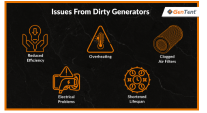
Electrical Overload: Operating the generator beyond its rated capacity increases current flow, which generates excessive heat in the alternator and windings. Can damage insulation, reduce efficiency, and lead to overheating of internal components.
Insufficient Cooling: A failure or inefficiency in the cooling system (e.g., blocked air vents, low coolant levels, or malfunctioning fans). Prevents the dissipation of heat, causing internal temperatures to rise.
Poor Ventilation: Operating the generator in a confined or poorly ventilated space can trap hot air, reducing the cooling effect. Leads to recirculation of hot air, causing the generator to overheat.
Mechanical Friction: Inadequate lubrication of moving parts, such as bearings or gears, increases friction and generates heat. Leads to wear and tear, potential component failure, and overheating.
Dirty or Clogged Filters: Air or fuel filters clogged with dust and debris restrict airflow and fuel supply. Reduces cooling efficiency and engine performance, leading to overheating.
High Ambient Temperatures: Operating the generator in hot climates or extreme heat increases the starting temperature of the cooling air or liquid. Limits the cooling system’s ability to reduce internal heat.
Short Circuits or Electrical Faults: Internal electrical faults, such as short circuits or ground faults, cause excessive current flow and heat generation. Can severely damage the alternator and other electrical components.
Blocked or Malfunctioning Exhaust: A blocked exhaust system prevents proper release of heat and combustion gases. Increases engine temperature and reduces overall efficiency.
Overuse or Continuous Operation: Running the generator for extended periods without breaks can cause heat to build up, especially if the cooling system is not designed for prolonged use. Gradual overheating and potential failure of key components.
Low Quality or Contaminated Fuel: Poor-quality fuel or contaminants in the fuel can cause inefficient combustion, increasing engine heat. Leads to residue buildup and reduced engine cooling efficiency.
Misaligned Components: Misaligned rotors, stators, or other mechanical parts can create additional friction or electrical resistance. Generates excess heat and wears out components faster.
Faulty Insulation: Worn or degraded insulation in the generator’s windings reduces resistance to heat and current flow. Leads to short circuits and increased heat generation.
Frequent Starting and Stopping: Repeated starts and stops without allowing the generator to reach stable operating temperatures. Causes uneven heating and stress on components.
Poor Maintenance: Lack of regular maintenance (e.g., failure to clean filters, check oil levels, or inspect cooling systems). Leads to buildup of heat due to reduced efficiency and unresolved mechanical or electrical issues.
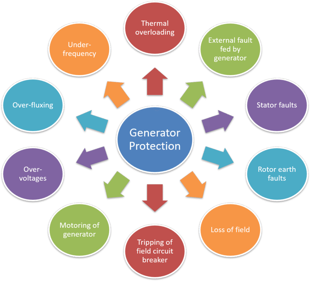
Generator Protection
A generator is exposed to multiple stresses during operation, including electrical stresses on its insulation, mechanical forces acting on its components, and temperature rises. These factors make it essential to provide proper protection for the generator or alternator. Even under optimal usage and in perfect running condition, a generator is designed to maintain its rated performance for years and can occasionally withstand certain overloads. However, protective measures are necessary to ensure safety and longevity.
Preventive measures must be implemented to guard against overloads and abnormal operating conditions. Despite efficient design, robust construction, proper operation, and preventive protection, the risk of faults cannot be entirely eliminated in any machine. To mitigate this, protection devices are employed to detect and eliminate faults as quickly as possible, minimizing damage and ensuring safe operation.
Generators can encounter internal faults, external faults, or a combination of both. Since generators are typically connected to an electrical power system, any fault in the system must also be addressed promptly. Failure to do so may result in severe or permanent damage to the generator.
Given the wide range of potential faults, generators are equipped with multiple protective schemes. Protection schemes can be either discriminative or non-discriminative, with careful coordination of systems and settings to achieve a sensitive, selective, and effective protection system. This ensures that faults are managed with precision, minimizing disruptions and safeguarding the generator’s operation.
Types of Generator Protection
The protection systems for generators can be broadly categorized into two types:
- Protective relays to detect external faults: These relays address issues occurring outside the generator but affecting its operation.
- Protective relays to detect internal faults: These relays handle faults that originate within the generator itself.
In addition to these protective relays, other devices are integrated to ensure the generator’s safety and reliability. These include lightning arrestors, overspeed safeguards, oil flow monitors, and temperature measuring devices for components such as shaft bearings, stator windings, transformer windings, and transformer oil.
Some of these protective mechanisms are non-trip types, which generate alarms during abnormal conditions without interrupting the operation. whilst are designed to activate the master tripping relay, shutting down the generator in critical situations. It is important to note that protective relays cannot prevent faults; their primary function is to detect and minimize the duration of faults. By doing so, they help prevent excessive temperature rise that could otherwise cause permanent damage to the generator.
To reduce undue stresses on the generator, devices such as surge capacitors and surge diverters are commonly installed. These components mitigate the effects of lightning and other voltage surges, protecting the machine from potentially harmful impacts.
Protection against Insulation Failure: Insulation failure in a generator can lead to severe consequences, such as short circuits, overheating, or even complete breakdown of the machine. Therefore, various protection mechanisms are employed to detect and mitigate insulation issues promptly. Below are the key strategies for protecting a generator against insulation failure:
Differential Protection: Detects phase-to-phase or phase-to-ground faults caused by insulation breakdown within the stator windings. Compares current entering and leaving the generator’s windings. Any discrepancy indicates a fault, triggering a trip to isolate the generator. Highly sensitive and effective for detecting internal faults.
Earth Fault Protection: Identifies insulation failure that leads to ground faults. Monitors the flow of fault current to the ground. Can be set up as a restricted earth fault (REF) scheme or an unrestricted one. Protects against ground faults caused by insulation failure, especially in stator windings.
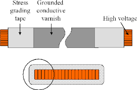
Stator Winding Temperature Monitoring: Prevents overheating due to insulation degradation. Embedded temperature sensors (e.g., resistance temperature detectors or thermistors) monitor the stator winding temperature. Alarms or trips are activated if temperatures exceed safe limits. Early detection of overheating prevents further insulation damage.
Overvoltage Protection: Protects against excessive voltage that could deteriorate insulation. Monitors voltage levels; activates alarms or trips when voltage exceeds set limits. Reduces the risk of insulation breakdown caused by overvoltage.
Surge Protection: Protects the generator from transient voltage spikes caused by lightning or switching operations. Devices such as surge arresters and surge capacitors absorb or divert excess energy to prevent voltage stress on the insulation. Reduces the impact of high-voltage surges on insulation integrity.
Insulation Resistance Monitoring: Monitors the condition of insulation over time to detect early signs of degradation. Measures the insulation resistance between windings and ground.A drop in resistance below a threshold triggers alarms or maintenance actions. Provides predictive maintenance capabilities.
Rotor Insulation Protection: Protects rotor windings from insulation failure. Monitors resistance or continuity of rotor insulation. Alarms are triggered if resistance falls below a critical level. Helps prevent rotor-related faults due to insulation breakdown.
Periodic Maintenance and Testing: Ensures insulation remains in good condition. Conduct regular insulation resistance tests (e.g., Megger testing). Perform polarization index tests to assess insulation aging.Inspect for physical damage, such as cracks or wear in insulation. Prevents faults by identifying issues early.
Use of High-Quality Insulation Materials: Minimizes the likelihood of insulation failure. Use thermally and electrically durable insulation materials. Ensure proper application and curing during installation. Enhances the generator’s reliability and longevity.
Alarm and Trip Mechanisms: Alerts operators and isolates the generator during insulation failure. Protective relays are configured to generate alarms or trip the generator in case of abnormal insulation conditions. Prevents catastrophic damage by timely fault isolation.
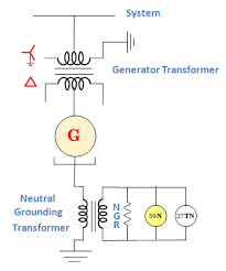
Stator Earth Fault Protection: When the stator neutral is grounded through a resistor, a current transformer (CT) is installed in the connection between the neutral and earth. For generators directly connected to a bus bar, an inverse time relay is used across the secondary of the CT. Conversely, if the generator supplies power through a delta-star transformer, an instantaneous relay is employed for the same purpose.
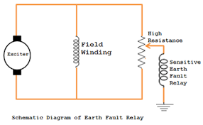
Rotor Earth Fault Protection: A single earth fault in a generator’s rotor does not usually cause significant issues. However, if a second earth fault occurs, it can short-circuit a portion of the field winding. This results in an unbalanced magnetic field, which can lead to severe mechanical damage to the generator’s bearings.
To detect such faults in the rotor, three primary methods are commonly used:
- Potentiometer Method
- AC Injection Method
- DC Injection Method
Each method is designed to identify faults efficiently, ensuring the generator operates safely and reliably.
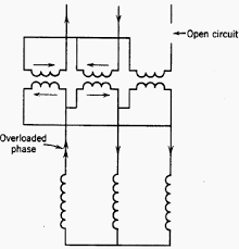
Unbalanced Stator Loading Protection: Unbalanced loading in a generator leads to the generation of negative sequence currents in the stator circuit. These currents create a reaction field that rotates at twice the synchronous speed relative to the rotor, inducing a double-frequency current in the rotor. This induced current is significantly large and can cause overheating in the rotor, especially in alternators. If the unbalance is caused by a fault in the stator winding, it is quickly cleared by the differential protection system in the generator. However, if the unbalance is due to an external fault or uneven loading in the system, it may persist for an extended period, depending on the coordination of the system’s protective devices. To address such scenarios, a negative phase sequence (NPS) relay is installed. This relay is designed to detect negative sequence currents and operates in accordance with the machine’s withstand curve, ensuring timely fault clearance while protecting the generator from overheating and damage.
Protection against Stator Overheating: Overloading can lead to overheating in the stator windings of a generator. In addition to overloading, factors such as cooling system failure and insulation failure in the stator laminations can also cause overheating.
To detect overheating, embedded temperature detectors are installed at various points in the stator winding. These detectors are typically resistance elements forming one arm of a Wheatstone bridge circuit, allowing precise temperature monitoring. However, smaller generators, typically below 30 MW, are usually not equipped with embedded temperature detectors. Instead, they are fitted with thermal relays designed to measure the current flowing through the stator windings.
This arrangement only identifies overheating caused by overloading and does not offer protection against overheating resulting from cooling system failures or short-circuited stator laminations. To enhance thermal protection, devices such as overcurrent relays, negative phase sequence relays, and flow-monitoring devices are employed. While these provide some degree of thermal overload protection, they may not cover all potential overheating scenarios.
Low Vacuum Protection: This protection system, typically in the form of a regulator that compares vacuum levels against atmospheric pressure, is commonly installed in generator sets above 30 MW. In modern setups, the regulator works by unloading the generator via the secondary governor until normal vacuum conditions are restored. If the vacuum level does not improve and drops below 21 inches, the system automatically closes the stop valves and trips the main circuit breaker to protect the generator from potential damage.
Protection against Lubrication Oil Failure: This protection is generally not deemed essential, as the lubrication oil and governor oil are typically supplied by the same pump. In the event of a governor oil failure, the stop valve will automatically close, providing inherent protection.
Protection against Loss of Boiler Firing: Two methods are commonly used to detect the loss of boiler firing:
Fan Motor Monitoring: Normally open (NO) contacts are installed on the fan motors. If more than two motors fail, these contacts trigger a trip to shut down the generator.
Boiler Pressure Monitoring: Pressure contacts monitor the boiler pressure. If the pressure drops below approximately 90% of the normal level, the system automatically unloads the generator to prevent further issues.
Protection against Prime Mover Failure: If the prime mover fails to supply mechanical energy to the generator, the generator will enter a motoring mode. In this mode, it draws electrical energy from the system instead of supplying it. In a steam turbine, steam serves as a coolant, maintaining the turbine blades at a stable temperature. When the steam supply fails, the lack of cooling causes the turbine blades to overheat due to friction, potentially leading to distortion and severe mechanical damage. Additionally, this failure imposes a significant motoring load on the generator. To protect against such scenarios, a reverse power relay is employed. The relay detects when the generator begins to operate in motoring mode and promptly trips the generator set to prevent further damage and system instability.
Over Speed Protection: While it is common practice to equip both steam and hydro turbines with mechanical overspeed devices that act directly on the steam throttle valve or main stop valve, it is not standard to back up these devices with an overspeed relay in steam-driven sets. However, in hydroelectric units, using an overspeed relay is considered good practice. This is because the governor’s response is relatively slower in hydro systems, making them more susceptible to overspeed conditions. When installed, the relay is typically powered by the permanent magnet generator that supplies the governor control system.
Protection against Rotor Distortion: After a shutdown, the cooling rates at the top and bottom of the turbine casing differ, leading to uneven temperature distribution that can damage the rotor. To mitigate this issue, it is standard practice to rotate the rotor at a low speed during the cooling period to ensure even temperature distribution. Given the significant forces involved with large modern rotors, it has become standard to equip turbines with shaft eccentricity detectors to monitor and address any imbalance during this process.
Protection against Difference in Expansion between Rotating and Stationary parts: During the run-up period, the rotor and casing of the turbine heat at different rates due to their varying masses. This results in unequal expansion between the rotor and casing, which must be managed to prevent mechanical stress. To address this, larger machines often feature independent steam supplies directed to specific joints on the casing. This allows for controlled heating to minimize expansion disparities. It is therefore essential to provide a means of measuring axial expansion to guide the operator in directing steam appropriately and to monitor for any dangerous levels of expansion. The shaft axial expansion detector is designed for this purpose. It operates similarly to rotor distortion monitoring equipment, with the primary difference being that its detector magnets are fixed to the turbine casing. This setup enables precise monitoring of axial expansion and assists in maintaining safe operation.
Protection against Vibration: Vibration detectors are typically installed on the bearing pedestals of a machine. Each detector consists of a coil mounted on springs, positioned between U-shaped permanent magnets. As the machine vibrates, the coil moves relative to the magnets, generating a voltage proportional to the level of vibration. This voltage signal is then sent through integrating circuits and displayed on an interval-indicating instrument, providing real-time measurement of vibration intensity.
Back up Protection of Generator: Backup protection is essential for highly rated machines like synchronous generators or alternators. In cases where primary protection fails to clear a fault, backup protection relays are designed to operate and isolate the fault. Overcurrent relays are commonly used for this purpose. However, due to the high synchronous reactance of modern machines, often exceeding 100%, the sustained fault current supplied by the generator to an external fault is typically lower than its normal full-load current. This creates challenges for standard Inverse Definite Minimum Time (IDMT) relays, as their current settings must be close to the full-load current, with short time settings to ensure operation. This can lead to a lack of discrimination with other overcurrent relays in the system. Additionally, conventional overcurrent relays may respond to events like loss of field, causing premature disconnection of the generator. To address these issues, it is common practice to use an overcurrent relay in combination with an undervoltage relay. The undervoltage relay adjusts the fault settings of the overcurrent relay, ensuring proper coordination and reducing the likelihood of misoperation. This combination provides reliable and effective backup protection for synchronous machines.
Interested in our Electrical Engineering Courses?
At iLearn Engineering®, we offer a diverse range of online accredited electrical engineering courses and qualifications to cater to different academic and career goals. Our courses are available in varying credit values and levels, ranging from 40 credit Engineering Diplomas to a 360 credit International Graduate Diploma.
Short Courses (40 Credits)
A selection of our more popular 40 credit electrical diplomas…
Diploma in Electrical and Electronic Engineering
Diploma in Electrical Technology
Diploma in Renewable Energy (Electrical)
First Year of Undergraduate (Level 4 – 120 Credits)
Higher International Certificate in Electrical and Electronic Engineering
First Two Years of Undergraduate (Level 5 – 240 Credits)
Higher International Diploma in Electrical and Electronic Engineering.
Degree equivalent Graduate Diploma (Level 6 – 360 Credits)
International Graduate Diploma in Electrical and Electronic Engineering
All Electrical and Electronic Courses
You can read more about our selection of accredited online Electrical and Electronic Engineering courses here.
Complete Engineering Course Catalogue (all courses)
Alternatively, you can view all our online engineering courses here.
Recent Posts
Civil Engineering Courses and Diplomas: Topics, Skills and Career Routes
Civil Engineering Courses and Diplomas: Topics, Skills and Career Routes Introduction Civil engineering is the backbone of modern society. From roads and bridges to skyscrapers and water systems, civil engineers design, build, and maintain the infrastructure that keeps the world running. If you’re considering a civil engineering course or diploma, understanding what it covers is […]
What Is a Diploma in Engineering? Courses, Levels and Career Routes Explained
What Is a Diploma in Engineering? Courses, Levels and Career Routes Explained Introduction Engineering shapes the world around us, from the buildings we live in to the technology we use every day. But for many aspiring engineers, the biggest question is not whether to pursue engineering, but how to start. Traditional university degrees are not […]
Engineering Courses: How to Choose the Right Route for Your Career
Engineering Courses: How to Choose the Right Route for Your Career Introduction Choosing an engineering course can feel like standing at the beginning of several different roads, each leading towards a different kind of future. One route may lead into mechanical systems and manufacturing. Another may lead towards aircraft, infrastructure, electronics, computing, renewable energy or […]