Understanding and Calculating Generator Efficiency and Output Parameters
Introduction
The performance of a generator is often judged by how efficiently it converts mechanical energy into electrical energy. Understanding and calculating this efficiency, along with other key output parameters such as voltage, current, power factor, and load, is essential for evaluating performance and ensuring reliable operation. In this article, we’ll explain the main measurable quantities related to generators, how they’re calculated, and what they reveal about a generator’s overall effectiveness.
Hopkinson Test
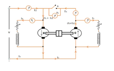
The Hopkinson Test, also known as the Back-to-Back Test, is a method used to determine the efficiency and losses of two identical DC machines (one acting as a motor and the other as a generator) under load conditions. It is a practical and efficient way to test machines without wasting a lot of power.
The test requires two identical machines: One machine operates as a motor, while the other operates as a generator. The two machines must be identical in design and rating. The armatures of the two machines are connected together, and their field windings are excited by external sources. The test simulates full-load conditions, allowing the machines to be tested at rated capacity. The power supplied from the mains is minimal because most of the power circulates between the two machines.
The test helps calculate the efficiency of the machines by measuring losses such as friction, windage, and electrical losses.
Procedure: Connect the armatures of the two machines together. Use a DC supply to excite the field windings. One machine is started as a motor using an external power supply. The motor drives the second machine, which operates as a generator. The generator feeds its output back to the motor. This creates a circulating load, minimizing the power drawn from the mains. Measure the input power, field current, and any additional losses. Use these measurements to calculate the efficiency and losses.
Advantages: Economical as they require only a small power supply since most power is circulated between the machines. Full-Load Testing simulates full-load conditions without requiring a large load bank. Accurate efficiency measurement provides precise results by separating losses.
Disadvantages: Both machines must be identical, which may not always be practical. Requires careful setup and balancing for proper operation.
Applications
- Testing the efficiency of DC motors and generators.
- Verifying the performance of machines in industries.
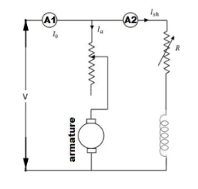
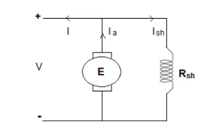
Connection Diagram of Hopkinson’s Test: Here is the circuit configuration for Hopkinson’s test, illustrated in the accompanying figure. The setup involves a motor and a generator, both of which are identical and mechanically coupled. Initially, the machine is started as a motor, with its shunt field resistance adjusted to ensure it runs at its rated speed.
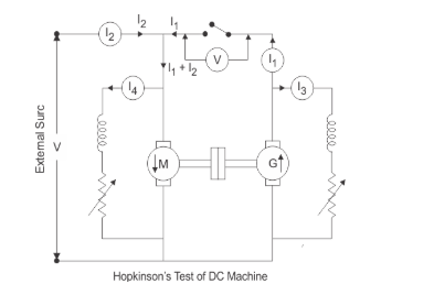
Next, the generator’s voltage is brought to match the supply voltage by fine-tuning the shunt field resistance connected across the generator. This voltage equality is confirmed by a voltmeter connected across a switch; when the voltmeter reads zero, it indicates the generator voltage equals the supply voltage.
By varying the field currents of the motor and generator, the machine operates at its rated speed and can achieve the desired load conditions. This arrangement allows for an efficient and controlled testing process.
Calculation of Efficiency by Hopkinson’s Test
To perform calculations in the Hopkinson Test, you primarily focus on determining the losses, efficiency, and overall performance of the motor and generator. Here’s how the key calculations are performed:
Key Measurements Required
Input Power (Pin): Power supplied to the motor-generator set from the supply.
Field Current for Motor (IfM) and Field Current for Generator (IfG): Current through the field windings of the motor and generator.
Line Current (Iline): Current drawn from the supply.
Armature Current (IaM and IaG): Armature currents for the motor and generator.
Supply Voltage (Vsupply): Voltage supplied to the motor-generator set.
Calculations
Total Power Supplied
Pin=Vsupply× Iline
Where: Vsupply = Supply voltage, Iline = Line current.
Power Loss in Field Circuits: The power loss in the field circuits is calculated separately for the motor and generator:
Pfield = V supply×(IfM + IfG)
Total Losses: The power supplied minus the field losses gives the total losses in the motor-generator set:
Ptotal losses=Pin − Pfield
Stray Losses: Assuming the stray losses are equally distributed between the motor and generator:
Stray loss (for one machine) = Ptotal losses / 2
Efficiency of the Motor: To find the efficiency of the motor:
ηmotor = Output power of motor/ Input power of motor
ηmotor= (Pin−Ptotal losses) / Pin
Efficiency of the Generator: To calculate the generator efficiency:
ηgenerator = Output power of generator / Input power of generator = Generator output / Motor output
Example 1:
Given: Vsupply= 220 V, Iline = 10 A, IfM = 1.5 A, IfG = 1.0A
Total Input Power
Pin = 220 × 10 = 2200 W
Field Losses
Pfield = 220 × (1.5+1.0) = 220 × 2.5 = 550 W
Total Losses
Ptotal losses = 2200 − 550 = 1650 W
Stray Loss (Per Machine)
Stray loss = 1650/ 2 = 825 W
Efficiency of Motor
ηmotor= (2200 − 1650) / 2200 = 550 / 2200 = 0.75 (75%)
Efficiency of Generator: Assuming generator output is similar to motor input:
ηgenerator = ηmotor = 75%
Advantages of Hopkinson’s Test This test requires very small power compared to full-load power of the motor-generator coupled system. That is why it is economical. Large machines can be tested at rated load without much power consumption. Temperature rise and commutation can be observed and maintained in the limit because this test is done under full load condition. Change in iron loss due to flux distortion can be taken into account due to the advantage of its full load condition. Efficiency at different loads can be determined.
Disadvantages of Hopkinson’s Test It is difficult to find two identical machines needed for Hopkinson’s test. Both machines cannot be loaded equally all the time. It is not possible to get separate iron losses for the two machines though they are different because of their excitations. It is difficult to operate the machines at rated speed because field currents vary widely.
Example 2:
Two shunt machines loaded for the Hopkinson’s test take 15A at 200V from the supply. The motor current is 100A and the shunt currents are 3A and 2.5A. If the armature resistance of each machine is 0.05 Ω. Calculate the efficiency of each machine for this particular load-condition.
Solution: To calculate the efficiency of each machine in the Hopkinson’s test, let’s proceed step by step with the given data.
Given Data: Supply voltage (Vsupply ): 200 V, Supply current (Iline): 15 A, Motor armature current (IaM): 100 A, Shunt current for the motor (IshM): 3 A, Shunt current for the generator (IshG): 2.5 A, Armature resistance (Ra): 0.05 Ω
Armature Current for the Generator (IaG)
From Kirchhoff’s current law:
Iline = IaG + IshM + IshG
IaG = Iline − (IshM + IshG)
IaG = 15 − (3 + 2.5 ) = 9.5 A
Copper Losses: The total copper loss in both machines is:
Pcu (total) = IaM 2 × Ra + IaG2 × Ra
Pcu (total) = (100)2 × 0.05 + (9.5)2 × 0.05
Pcu (total) = 500 + 4.5125 = 504.51 W
Shunt Field Losses: The total shunt field loss is:
Psh (total) = Vsupply × (IshM + IshG)
Psh (total) = 200 × (3 + 2.5) = 200 × 5.5 = 1,100 W
Total Losses: The total losses are:
Ptotal losses = Pcu (total) + Psh (total)
Ptotal losses = 504.51 + 1,100 = 1,604.51 W
Output Power: The input power from the supply is:
Pin = Vsupply × Iline
Pin = 200 × 15 = 3,000 W
The total output power is:
Pout = Pin − Ptotal losses)
Pout = 3,000 − 1,604.51 = 1,395.49 W
Efficiency of Each Machine: The efficiencies of the motor and generator can be assumed approximately equal, as they are identical machines.
The efficiency of each machine is:
η = Output Power of One Machine / Input Power of One Machine
The output power of one machine is half of the total output power:
Pout (one machine) = Pout / 2 = 1,395.49 / 2 = 697.75 W
The input power of one machine is:
Pin (one machine) = Pout (one machine) + Plosses (one machine)
The losses for one machine are half of the total losses:
Plosses (one machine) = Ptotal losses / 2 = 1,604.51 / 2 = 802.26 W
The efficiency is:
Pin (one machine) = 697.75 + 802.26 = 1,500.01 W
η = Pout (one machine) / Pin (one machine) x 100
η = 697.751,/ 500.01×100 = 46.5%
Final Efficiency:
The efficiency of each machine is approximately:
46.5%
EMF Equation of DC Generator
The EMF equation of a DC generator describes the relationship between the parameters of the machine and the electromotive force (EMF) generated. Here’s a step-by-step derivation:
Induced EMF of One Armature Conductor
From Faraday’s Law of Electromagnetic Induction, the induced EMF is proportional to the rate of change of magnetic flux linkage. For a conductor rotating in a magnetic field: Φ = Flux per pole (in Weber, Wb), P= Number of poles
Total flux per revolution = Φ × P
The time for one revolution is:
t = 60 / N (in seconds, where N is the speed in rpm).
Now, the rate of flux cutting (induced EMF, e) in one conductor is:
e = Total flux / Time for one revolution = Φ × P / 60/N) = Φ × P × N/60
Thus, the induced EMF in one conductor is:
e = Φ × P × N / 60 (volts).
Induced EMF of the DC Generator
Let: Z = Total number of armature conductors, A = Number of parallel paths, Z / A = Number of conductors in series per parallel path
The total induced EMF (E) across each parallel path is:
E = Induced EMF of one conductor × Conductors in series per path.
Substituting the expressions:
E = e x Z/A = (Φ × P × N) /60 × Z/A
Simplify:
E = Φ × P × N × Z/ (60xA).
This is the general EMF equation of a DC generator.
Special Cases of Winding Types
(a) Wave Winding: For wave winding, the number of parallel paths (A) is always 2.
Ewave = Φ × P × N × Z/ (60×2)
(b) Lap Winding: For lap winding, the number of parallel paths (A) equals the number of poles (P).
Elap = Φ × P × N × Z / (60xP)
Simplify:
Elap = Φ × N × Z / 60
Example 3:
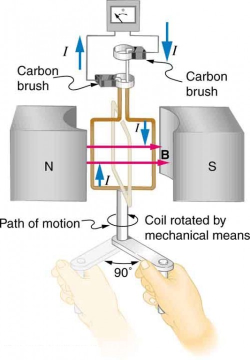
The generator coil in the diagram is rotated through one-fourth of a revolution( from 𝚹 = 0º to 𝚹=90º in 15.9 ms. The 200-turn circular coil has a 5.00cm radius and is in a uniform 1.25T magnetic field .a) What is the average emf induced? b) maximum emf?
To solve this problem, we will calculate both the average EMF induced during the quarter revolution and the maximum EMF that the generator can produce.
Given Data: N = 200 (Number of turns), r = 5.00 cm = 0.05 m (Radius of the coil), B =1.25 T (Magnetic field strength), Time interval for Δθ = 90º = π / 2 radians, Δt =15.9 ms = 15.9×10⁻³ s
Average EMF Induced: The EMF is given by Faraday’s law of induction:
E = −N x (ΔΦ / Δt)
where ΔΦ is the change in magnetic flux through the coil.
Magnetic Flux (Φ): The flux through one loop is:
Φ = BAcosθ
where A=πr2 is the area of the loop.
For N turns:
Φtotal = N × B × A cosθ
Φinitial = N × B × A cos0º = N × B × A
Final flux at θ=90º
Φfinal = N × B × A cos90º =0
Change in flux:
ΔΦ = Φfinal − Φinitial = 0 − N × B × A = − N × B × A
Substitute values:
A = πr2 = π(0.05)2 = 7.854×10⁻³ m2,
ΔΦ = − N × B × A = − (200) × (1.25) × (7.854×10−3)
ΔΦ = − 1.9635 Wb
Average EMF:
Eavg = −ΔΦ / Δt = −1.9635/ 15.9×10−3 = 123.5 V
Maximum EMF: The maximum EMF is given by:
Emax = N x B x A x ω
where ω is the angular velocity of the coil:
ω = Δθ/ Δt = π/2/−3)= 98.8 rad/s.
Substitute values:
Emax = N x B x A x ω,
Emax = 200 × 1.25 × 7.854×10−3 × 98.8
Emax=193.8 V.
Example 4
A four pole generator having wave-wound armature winding has 51 slots, each slot containing 20 conductors. What will be the voltage generated in the machine when driven at 1500 rpm assuming the flux per pole to be 7.0 mWb ?
Solution:
To calculate the voltage generated in the machine, we will use the EMF equation for a DC generator:
E = Φ × P × N × Z /(60xA)
where:: E = Generated EMF (volts), Φ = 7.0 mWb = 7.0×10⁻³ Wb (Flux per pole) , P =4 (Number of poles), N = 1500 rpm (Speed of armature), Z = Total number of conductors = Number of slots × Conductors per slot, A=2 (Wave winding has 2 parallel paths).
Step-by-Step Calculation:
Calculate Z, the total number of conductors:
Z = Slots × Conductors per slot
Z = 51×20=1020.
Substitute values into the formula:
E = Φ × P × N × Z / (60xA)
Substituting:
E = (7.0×10−3) × 4 × 1500 × 1020 / (60×2)
E = 357 V
The voltage generated in the machine is:
E = 357 V.
Power Stage in a DC Generator
The power stage in a DC generator is represented by the figure below.
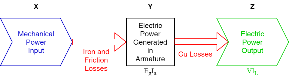
In the power stage of a DC generator, the efficiency at different levels is described based on the conversion and losses occurring during operation.
In a DC generator, power flow and losses are typically divided as follows: Input mechanical power is supplied to the generator through the prime mover.
Losses are split into: Iron and friction losses (core losses, windage, and friction losses): represented as Y−X Copper losses (losses in the armature and field windings due to current flow): represented as Z−Y
Output electrical power is delivered to the load.
Efficiencies in a DC Generator
(a) Mechanical Efficiency: Mechanical efficiency accounts for the losses between the mechanical power input and the electrical power generated. It is given by:
ηmech = Eg x Ia / Pmechanical x 100%
Where: Eg: Generated voltage in the armature, Ia: Armature current, Pmechanical input :Total mechanical power supplied to the machine.
(b) Electrical Efficiency: Electrical efficiency considers the losses in the electrical components of the generator, primarily copper losses. It is defined as:
ηelectrical = Puseful electrical output / ( Eg x Ia) x 100%
Where: Puseful electrical output = VL x IL , Eg x Ia : Total electrical power generated by the armature.
(c) Commercial (Overall) Efficiency: The overall efficiency includes all losses (mechanical, iron, friction, and copper) and measures the ratio of the electrical power output to the total mechanical power input:
ηoverall = Puseful electrical output / Pmechanical inputx 100%
Using the above relationships, we can connect the different efficiencies:
ηoverall = ηmech × ηelectrical
Power Flow Summary
Input Mechanical Power:
Pmechanical input = Pcore losses + Pcopper losses + Puseful electrical output
Core Losses (Y−XY): Combination of iron, windage, and friction losses.
Copper Losses (Z−Y): Primarily resistive losses in the armature and field windings.
Output Electrical Power:
Puseful electrical output = VL x IL
Summary: Losses in a DC Generator
Copper Losses: Copper losses occur due to the flow of current through the windings of the DC generator. These losses arise in both the armature winding and the field winding.
Iron Losses (Core Losses): Iron losses occur in the armature as it rotates within the magnetic field. These losses are categorized into:
Hysteresis Loss:: Hysteresis loss occurs due to the magnetic reversals in the armature during each half rotation. It is given by:
Physteresis = η x Bm1.6 x f x V
Where: Bm: Maximum flux density in the armature core, f: Frequency of magnetic reversal f = (N x P) / 120 ; (where N is in RPM), V: Volume of the armature, η: Steinmetz hysteresis coefficient.
Eddy Current Loss: Eddy current loss is caused by circulating currents induced within the armature core as it rotates in the magnetic field. This loss is given by:
Peddy = Ke x Bm2 x f2 x t2 x V
Where: Ke: Constant, Bm: Maximum flux density in the armature core, f: Frequency of magnetic reversal, t: Thickness of the lamination, V: Volume of the core.
Mechanical Losses: Mechanical losses arise from friction and windage.
Friction losses: Due to bearing friction and brush contact friction.
Windage losses: Caused by air resistance acting on the rotating armature.
Combined Losses: Iron losses and mechanical losses are often grouped together as stray losses.
Interested in our Electrical Engineering Courses?
At iLearn Engineering®, we offer a diverse range of online accredited electrical engineering courses and qualifications to cater to different academic and career goals. Our courses are available in varying credit values and levels, ranging from 40 credit Engineering Diplomas to a 360 credit International Graduate Diploma.
Short Courses (40 Credits)
A selection of our more popular 40 credit electrical diplomas…
Diploma in Electrical and Electronic Engineering
Diploma in Electrical Technology
Diploma in Renewable Energy (Electrical)
First Year of Undergraduate (Level 4 – 120 Credits)
Higher International Certificate in Electrical and Electronic Engineering
First Two Years of Undergraduate (Level 5 – 240 Credits)
Higher International Diploma in Electrical and Electronic Engineering.
Degree equivalent Graduate Diploma (Level 6 – 360 Credits)
International Graduate Diploma in Electrical and Electronic Engineering
All Electrical and Electronic Courses
You can read more about our selection of accredited online Electrical and Electronic Engineering courses here.
Complete Engineering Course Catalogue (all courses)
Alternatively, you can view all our online engineering courses here.
Recent Posts
Civil Engineering Courses and Diplomas: Topics, Skills and Career Routes
Civil Engineering Courses and Diplomas: Topics, Skills and Career Routes Introduction Civil engineering is the backbone of modern society. From roads and bridges to skyscrapers and water systems, civil engineers design, build, and maintain the infrastructure that keeps the world running. If you’re considering a civil engineering course or diploma, understanding what it covers is […]
What Is a Diploma in Engineering? Courses, Levels and Career Routes Explained
What Is a Diploma in Engineering? Courses, Levels and Career Routes Explained Introduction Engineering shapes the world around us, from the buildings we live in to the technology we use every day. But for many aspiring engineers, the biggest question is not whether to pursue engineering, but how to start. Traditional university degrees are not […]
Engineering Courses: How to Choose the Right Route for Your Career
Engineering Courses: How to Choose the Right Route for Your Career Introduction Choosing an engineering course can feel like standing at the beginning of several different roads, each leading towards a different kind of future. One route may lead into mechanical systems and manufacturing. Another may lead towards aircraft, infrastructure, electronics, computing, renewable energy or […]