Breaking Down Aircraft Loads: Types and Real-World Applications
Introduction
An aircraft structure must be designed to withstand a large number of different types of loads. Some of these loads, such as towing, arresting, external stores, and landing gear loads, are applied to the structure at a few discrete locations. These are referred to as point loads or concentrated loads. Others, primarily the aerodynamic loads, are the result of pressures and shear stresses distributed over the aircraft surface, and hence called distributed loads.
These loads are not distributed uniformly, and the locations on aircraft surfaces where maximum pressure loads occur change as flight conditions change. Many of these loads are unsteady, conducive to structural fatigue. Before the detailed design of an aircraft structure can occur, the maximum magnitudes and frequencies of application of these many loads that the aircraft must sustain in order to meet the design requirements must be determined.
Types of Loads
An aircraft is basically required to support two types of basic loads:
Ground Loads : Encountered by the aircraft during movement on the ground; ie: taxying, landing, towing, etc
Air Loads : Loads exerted onto the structure during flight by the manoeuvres carried out by the aircraft or by wind gusts (such as wind shear).
As well as these, other role specific loads may be generated by the aircraft, ie:
- High Altitude Flying: Pressurised cabin,
- Amphibious aircraft:Landing on water,
- Military Aircraft : High Speed Manoeuvres, Withstand considerable damage
These two loads classes may be further divided into:
Surface Loads: Act on the surface of the structure, such as aerodynamic or hydrostatic loads, and
Body forces: Act over the volume of the structure and are generated by gravitational and inertia effects.
Point Loads
Maximum magnitudes of most concentrated loads can be determined fairly easily. Consider the case below of an aircraft on the ground
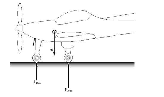
where: RNose is the ground reaction at nose wheel, RMain is the main undercarriage ground loads, W is the mass of aircraft acting at centre of gravity (= Mg)
Assuming a maximum towing load equal to 50% of the aircraft’s maximum takeoff weight would allow for the possibility of towing on steep inclines and uneven surfaces. Rolling friction and braking loads are given by the following
F = μR
Where F is the braking force (N), μ is the coefficient of rolling friction ( μ< 0.1 for a free-rolling wheel and μ< 0.6 for a braking wheel ) and R is the portion of the aircraft weight carried by each landing gear.
Aircraft are normally designed to place 10–12% of the aircraft weight on the nose gear and 88–90% distributed evenly between or among the main gear. However, the nose-down pitching moment created by braking will increase the nose-gear load, depending on the aircraft geometry. Likewise, any small turns made during braking can place more than 50% of the aircraft weight on one main gear. As a general rule for maximum rolling friction and braking load calculations, allow for the possibility of 50% of the total weight being on the nose gear and 100% on each main gear
Maximum side loads during turns are of approximately the same magnitude as braking loads. However, landing loads will be significantly higher than this.
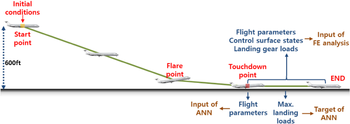
Worst-case landing loads require that the landing gear be able to sustain the forces necessary to absorb all of a maximum specified sink rate in the length of the landing-gear stroke as depicted below.
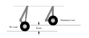
This can produce forces on each landing gear that are four or more times the total aircraft landing weight, especially for carrier-based aircraft.
Landing gear for land-based aircraft are generally designed for a maximum sink rate on landing of around 4m/s, whereas carrier-based aircraft are designed for around 8m/s sink rates. During a bad landing with significant bank and/or sideslip, a large portion of this load can be side load. Designers must make a trade-off between the extra weight associated with additional structural strength and heavier landing gear with longer stroke.
Point loads on the structure from externally or internally mounted stores, engines, equipment, passengers, and payload are simply the weight of the item and any pylons, seats, mounting brackets, etc. multiplied by the maximum load factor that the aircraft will sustain when these items are carried. The load as a result of drag of any external stores and the thrust of engines must also be considered, especially if they are hung on long pylons that cause the forces to produce strong twisting moments on the structure.
Many aerodynamic loads also apply point loads to portions of the structure. This occurs typically because lifting and control surfaces, though they sustain distributed aerodynamic loads, are designed to attach to the rest of the aircraft structure at only a few points. These surfaces essentially collect the distributed load and concentrate it into a few points. The maximum aerodynamic load on wing-to-fuselage attachment points results from the maximum lift the aircraft is designed to generate. For an aircraft designed to sustain a load factor of nine, the design maximum lift can be more than nine times the weight (depending on the magnitude and direction of trim lift generated by control surfaces). The drag and pitching moment generated by the wing in this condition also add to the load on the fuselage.
Control surfaces place similar lift, drag, and pitching-moment loads on an aircraft. In addition, control sticks, linkages, cables, and actuators place loads on the aircraft structure caused by the aerodynamic resistance to control surface movements that they must overcome. Attachment points for control systems must be very rigid to avoid sloppiness in the controls, which reduces control effectiveness.
Distributed Loads
Not all distributed loads on an aircraft structure are aerodynamic. Fuel is often carried within the wings in rubber bladders, or in integral fuel tanks portions of the structure that have been sealed against leaks.
Other types of liquids (water, fire-retardant chemicals, insect spray, etc.) can also be carried. Some of these liquids might be under pressure, adding to the magnitude of the distributed load. Typically, though, pressurized liquids and gases are carried in separate pressure vessels, which load the aircraft structure at discrete points. In addition to liquids, some other types of cargo (grain, gravel, etc.) also place distributed loads on the structure
Aerodynamic Loads
Pressure loads are generally of much greater magnitude than aerodynamic loads caused by shear. The highest air pressures are generally at stagnation points, where at high speeds and low altitudes. Low static pressures in regions of high flow velocities also place distributed loads on the structure.
Even when the pressure and shear loads on an airfoil are represented as lift-and-drag point loads at the airfoil’s centre of pressure, they still must be considered as a distributed load across the span of the wing
All flying aircraft flying under steady flight, manoeuvre or gust conditions experience pressure distributions on the surface of the skin. The resultant of these pressures cause direct loads such as: bending, shear and torsion in all parts of the structure.
The force on an aerodynamic surface (Wing, vertical & horizontal tail) results from a differential pressure distribution caused by incidence, camber or both.
For a typical wing, the chordwise pressure distribution looks like this:
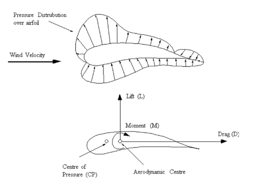
This wing with incoming wind direction as shown creates this pressure distribution. By integrating (adding up) the pressure in the vertical and horizontal components about the wind direction the following terms can be obtained:
a) The vertical Lift Force component (L), perpendicular to the wind direction.
b) The horizontal Drag component (D), parallel to the wind direction.
Both these resultant forces act through the centre of pressure of the aerofoil. But as this point will move depending on the attitude of the airfoil to the incoming wind, the lift and drag forces are moved to act about the aerodynamic centre (the quarter chord). This means that an extra Moment needs to be included to keep the system in equilibrium.
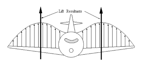
Looking at the wing in a spanwise view, the lift distribution about the AC is as shown below, where the wing Lift resultant forces act as shown.
Now that the pressures on the surfaces of an aircraft can be converted to loads, the overall loads on an aircraft due to symmetrical manoeuvres can be investigated.
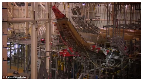
Remember, that aircraft wings are flexible structures, and are indeed designed to allow for bending.
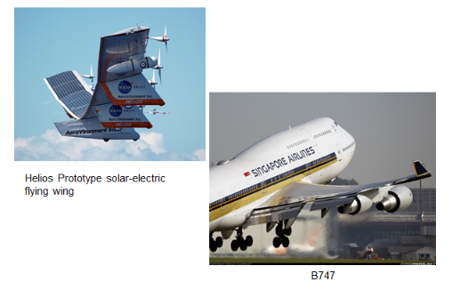
Wings are not just subject to aerodynamic loads and an obvious case of this is the load due to the weight of the engine. Below, we can see the testing of an aircraft wing to maximum bending: (A350XWB test campaign).
Gust Loads
For some aircraft, particularly transports, design maximum aerodynamic loads are not caused by manoeuvring but result from encounters with gusts or air turbulence.
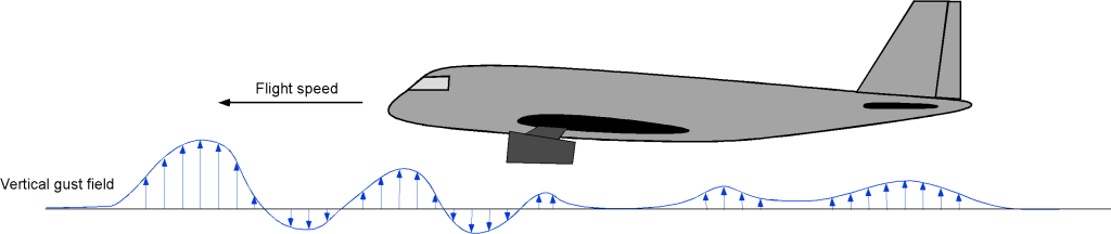
Gusts result from uneven heating of the Earth’s surface, which produces strong vertical air currents and winds in the atmosphere. Gusts also result from the strong trailing vortex systems shed in the wakes of large aircraft. The strongest gust load that aircraft are designed to sustain is one caused by an aircraft flying into a strong vertical air current, which abruptly changes its angle of attack and the lift it is producing. Airline passengers are frequently reminded of the effects of vertical gusts when the pilot turns on the “Fasten Seat Belts” sign.
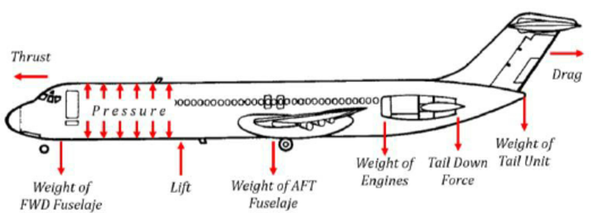
Fuselage Loads
The fuselage will experience a wide range of loads from a number of sources. The weight of the fuselage structure and payload will cause the fuselage to bend downwards from its support at the wing, putting the top in tension and the bottom in compression. In manoeuvring flight, the loads on the fuselage will usually be greater than for steady flight. During negative g-manoeuvres, some of the loads are reversed.
Also landing loads may be significant. The structure must be designed to withstand all loads cases. The bending loads are higher when the weight is distributed towards the nose and tail. Therefore, aircraft are loaded close to the centre of gravity.
Internal pressure will generate large bending loads in fuselage frames. The structure in these areas must be reinforced to withstand these loads. Because fuselages are pressurized for safety, the designer must consider what will happen if the pressurization is lost. The damage due to depressurization depends on the rate of pressure loss. For very high rates, far higher loads would occur than during normal operation.
Doors and hatches are a major challenge when designing an aircraft. Windows, being small, do not create a severe problem. Depending on their design, doors will or will not carry some of the load of the fuselage structure.
Load Factor, n
Many of the load requirements on aircraft are defined in terms of the load factor, n. The load factor is defined as the component of aerodynamic force perpendicular to the longitudinal axis divided by the aircraft weight. Assuming the angle of attack is not large, n = L/W. This is the effective perpendicular acceleration of the aeroplane in units of g, the acceleration due to gravity.
V-n Diagrams
A V-n diagram shows velocity against load factor, n. They can be useful to show the limitations an aircraft may have on its ability to generate the lift or sustain the structural loading needed to perform an acceleration manoeuvre. These limitations are often summarized on a chart known as a V-n diagram:
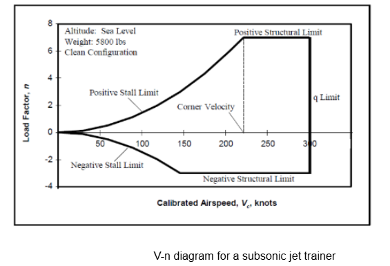
Maximum positive and negative load factors which the aircraft structure can sustain are shown as horizontal lines on the chart, since for this particular aircraft these structural limits are not functions of velocity.
At low speeds, the maximum load factor is limited by the maximum lift the aircraft can generate. Maximum lift boundary is also known as the stall boundary Vertical line which is labelled “q limit” indicates the maximum structural airspeed. In this case, the maximum structural airspeed is not a function of load factor
On many aircraft maximum structural speed decreases at high positive and negative load factors
The feature of the aircraft which sets the maximum speed varies.
For the aircraft here, the maximum speed limit is actually set by the aircraft’s critical Mach number. Flight above this speed is prohibited because shock-induced separation causes control difficulties.
For other aircraft, the limit is set by the structural strength required by the wings, windscreen, etc. to resist the high dynamic pressures and high stagnation point pressures at these speeds; Hence the name “q-limit.”
For many high-speed aircraft the maximum speed is actually a temperature limit, since at faster speeds skin friction and shock waves generate so much heat that the aircraft skin will melt!
Interested in our Aerospace Engineering Courses?
At iLearn Engineering®, we offer a diverse range of online accredited aerospace engineering courses and qualifications to cater to different academic and career goals. Our aerospace courses are available in varying credit values and levels, ranging from 40 credit Engineering Diplomas to a Bachelor’s equivalent 360 credit International Graduate Diploma.
All Aerospace Engineering Courses
All Aerospace Engineering Diploma Courses can be seen here.
Short Aerospace Courses (40 Credits)
- Diploma in Aerospace Engineering
- Diploma in Aircraft Design
- Diploma in Principles of Flight
- Diploma in Aerospace Structures
- Diploma in Aerodynamics
- Diploma in Aerodynamics, Propulsion and Space
First Year of Undergraduate (Level 4 – 120 Credits)
Higher International Certificate in Aerospace Engineering
Years One and Two of Undergraduate (Level 5 – 240 Credits)
Higher International Diploma in Aerospace Engineering
Degree Equivalent International Graduate Diploma (Level 6 – 360 Credits)
International Graduate Diploma in Aerospace Engineering
Complete Engineering Course Catalogue (all courses)
Alternatively, you can view all our online engineering courses here.
Recent Posts
Understanding Key Performance Indicators in Manufacturing
Understanding Key Performance Indicators in Manufacturing Introduction Key Performance Indicators (KPIs), or sometimes written as Key Performance Measures, are some of the key ‘metrics’ that are used to measure the performance of an industrial system. A good KPI for a manufacturing system should be SMART, that is: Specific – It should measure a specific output […]
How Aircraft Structures Evolved: From Fragile Flyers to Engineering Masterpieces
How Aircraft Structures Evolved: From Fragile Flyers to Engineering Masterpieces Introduction As with all other aspects involved with an aircraft, the structural design and layout has changed markedly over the history of flight, in line with technological advances and new discoveries. This section will highlight some of the more substantial developments made during the history […]
Why Lean Manufacturing Matters: Principles of waste
Why Lean Manufacturing Matters: Principles of waste Introduction Lean manufacturing isn’t just a toolkit for improving efficiency, it’s a mindset that reshapes how organisations think about value. At its core, lean focuses on delivering exactly what the customer needs, when they need it, with as little waste as possible. In an increasingly competitive and resource-conscious […]