How Aircraft Structures Evolved: From Fragile Flyers to Engineering Masterpieces
Introduction
As with all other aspects involved with an aircraft, the structural design and layout has changed markedly over the history of flight, in line with technological advances and new discoveries. This section will highlight some of the more substantial developments made during the history of manned flight and includes comments on the reasons behind the changes and any repercussions.
Earliest Aircraft
Wooden Biplanes
The earliest aircraft of all, of course, is the Wright Flyer (1903)
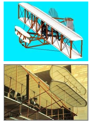
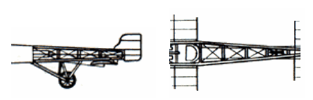
Early aircraft structures were based on simple yet efficient design principles using lightweight, readily available materials. The structure typically consisted of rectangular trussed frames with solid vertical struts and diagonal wire bracing, allowing loads to be distributed effectively while minimizing weight. Biplane wing configurations were favored as they provided greater strength and rigidity compared to early monoplanes. Tensile forces were carried by wire bracing, while compression loads were supported by a small number of structural members. Wings were formed using thin ribs covered with fabric, creating a lightweight aerodynamic surface. Materials such as wood (bamboo and later spruce), piano wire, and cotton muslin were used due to their low cost and ease of construction, reflecting the practical and resourceful engineering approaches of early aviation pioneers.
This was the dominant design for many years (until the mid 30’s) & such designs are still occasionally used, for the likes of aerobatics & crop-sprayer aircraft. The major structural advantages of the layout are high rigidity and consequently good bending and torsional resistance. This layout is suitable for aircraft with low wing loading (W/S) requirements (e.g. aerobatics types with good low-speed manoeuvrability needs). The layout results in a very light aircraft, typically only about 10% of the weight of an equivalent sized modern metal-skinned aircraft!
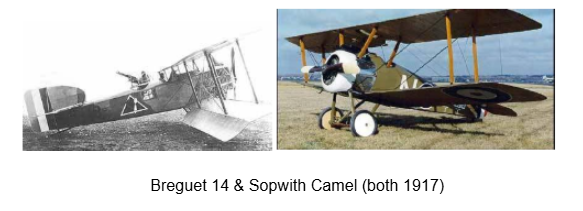
The majority of WWI aircraft were based upon this configuration
Wooden Monoplanes
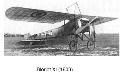
This new concept originated in Europe and included the use of a dedicated trussed fuselage and monoplane wing. The concept was largely ignored by the Britain aircraft manufacturing community due to conservatism and concerns over strength & durability. Some of the most prominent early aircraft to use this design approach were those of Louis Bleriot, the first to successfully undertake an aerial English Channel crossing.
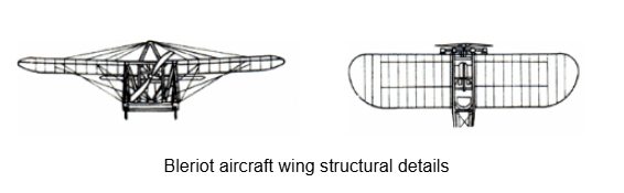
The wing structure comprised two thin wooden spars with external wire bracing to independently support lifting & landing tensile loads. The fuselage structure incorporated a standard civil engineering Pratt truss type of design, comprising 4 main longerons running down its length with additional support from spacers, struts & cross-wire bracing.
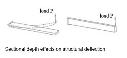
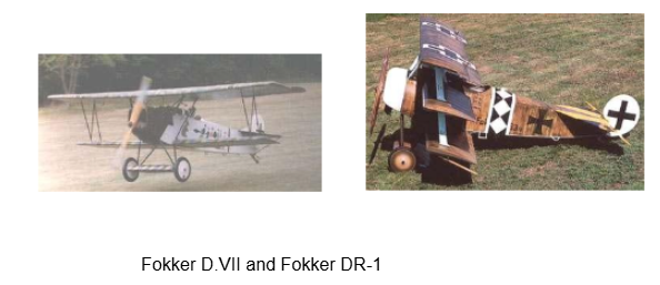
By the end of WWI (1918), certain aircraft structural design features were virtually standard. To improve lift, wings were now manufactured with much thicker sections and had much less lower surface curvature. This allowed for the use of deeper spars, thus improving wing second moment of area values and thus the overall wing strength and stiffness. This consequently removed the need for external wire bracing. Examples of such aircraft include the Fokker D.VII (1918) and Fokker DR-1 (1917).
The Use of Metal
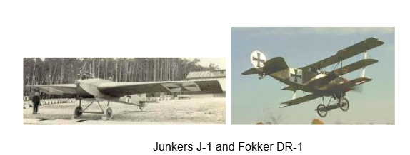
There was a fairly gradual change-over from the use of wood to the use of metal from WWI onwards, though the Junkers J-1 monoplane (1910) was built entirely from metal (steel tubing & thin sheet iron coverings) while the Fokker DR-1 triplane (1917) also used steel tubing for fuselage truss members.
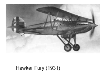
A major reason for the greater use and adoption of metal for the airframe was due to the short supply of spruce directly after WWI. It was a fairly gradual changeover, however, with some manufacturers reluctant to move away from their wood-working facilities and experience. For instance, a typical aircraft of the 1930’s, the Hawker Fury (1931) only used metal in the form of steel tubes for the main fuselage members, along with the usual cross-wire bracing. Wood was still used extensively elsewhere.
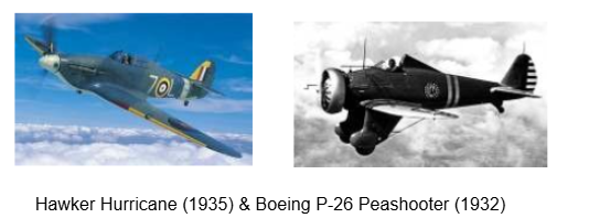
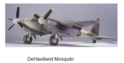
The change to all or mostly all metal construction was almost complete by the time of Hawker Hurricane (1935), and certainly prior to start of WWII in 1939. Some still used fabric coverings for the wing and/or fuselage, however, such as the Hurricane and Vickers Wellington. The most notable all-wooden aircraft by the time of WWII was the highly successful Mosquito fighter aircraft.
Stressed-Skin Construction
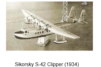
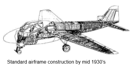
A major universal breakthrough in aircraft structural design occurred in the 1930’s, with the advent of stressed-skin or semi-monocoque construction methods. This arose because of the major problems caused by the standard internal cross-bracing in the fuselage as aircraft developed requirements to carry passengers & payload internally. Designers soon recognised that the designs applicable to flying boat fuselage construction were also appropriate for transport aircraft use. The main structural advantage is that the skin is then an integral load-carrying working part of the overall structure. The wording can be broken down into: “mono” – one piece, “coque” – skin or egg shell, “semi-” – makes use of additional internal stiffening framework.
This concept has been used on virtually all aircraft designed since 1930’s.
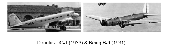
Soon after the fuselages came stressed-skin wings. This was mainly driven by the US designers, who were dominant in building large capacity transports & bombers at that time, e.g. the B-9 and B-10 bombers; the Boeing 247, DC-1, DC-2 and DC-3 airliners.
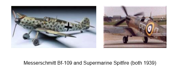
By this stage, the standard airframe was of aluminium alloy construction with a structural load- carrying skin riveted to frames, longerons (for fuselage) or spars (for wing), ribs & stringers. The European designers and manufacturers lagged behind their US counterparts by about 5 years, mainly because they were working on smaller aircraft and it was more difficult to scale down the stressed-skin technology. Messerschmitt (Germany) and Supermarine (UK) were the only Europeans making stressed-skin wings by the mid 1930’s.
Major Aerostructures Developments since WWII
Pressurised Fuselages
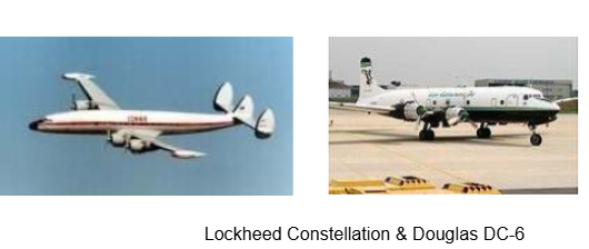
The use of cabin pressurisation in the mid 1940’s to improve the flying environment for passengers and crew led to considerably increased fuselage strength requirements. Some of the earliest aircraft to use pressurisation were the Lockheed Constellation, Douglas DC-6 and Boeing 377 Stratocruiser, all of which cruised at around 20,000 ft with cabin pressures equivalent to that experienced at 8,000 ft altitude. This directly led to the adoption of circular sections as the norm, minimisation of structural cut-outs & careful consideration and alleviation of stress concentrations (by using rounded fuselage door corners, etc.).
Aeroelasticity Problems
Rapid advances in aerodynamics & propulsion technology during the 1940’s led to higher speeds, more lift and increased wing loadings. As a direct result, several previously unknown aeroelastic phenomena became apparent for fighters during WWII, including: Wing and control surface flutter, Divergence, Control surface (especially aileron) reversal.
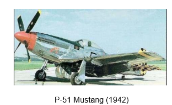
All of these problems forced the need for increased wing torsional (twisting) stiffness. A particular problem for WWII fighters was the lack of roll response in high speed dives – several aircraft (e.g. the Spitfire, P-51 Mustang, etc.) reduced the wing span in order to help alleviate the problem.
Manufacturing Techniques – Integral Construction
Increased aircraft speeds, allied with the advent of the turbojet propulsion era and design against metal fatigue, led to the need for thicker wing skins. These were consequently more difficult to wrap around the internal structural framework. By the 1950’s, the skins were usually pre-formed by rolling or, alternatively, by stretch-forming. By the late 50’s integral construction was commonly being used to form the skin and stringers as one. These would be machined from a solid slab of aluminium alloy with perhaps 95% of original material removed.
Advantages include:
- Less riveted fasteners so less wing drag.
- Fewer stress concentrations so reduced fatigue issues.
- Easier optimal tapering of skin thickness with weight benefits.
- Easier to seal fuel tanks.
- Improved fuel tank volume.
Metal Fatigue Problems
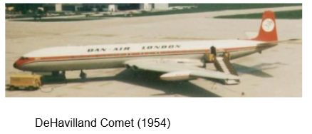
The potentially catastrophic effects of metal fatigue were highlighted for the aerospace community in 1954 when 2 DeHavilland Comet jet airliners disintegrated in flight within 3 months of each other. This can be mainly attributed to the non-consideration of low-cycle pressurisation & depressurisation and the resultant effects on weakening the structural strength (i.e. metal fatigue). The resultant cracks first appeared in areas of high stress concentrations, in these cases at the corners of the non-rounded windows, and soon propagated with disastrous consequences.
Subsequent aircraft fuselages were better designed to withstand such problems, through the use of: increased skin thicknesses, rounded windows, multiple load paths (“fail-safe” design), the use of crack-resistant copper-rich aluminium alloys and the increased use of welding, bonding, chemical etching and integrally machined panels.
High Speed Problems
Swept Wings
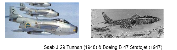
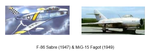
After WWII, major wing structural design changes were caused and forced by adopting Busemann’s wing sweep theory for reducing high-speed wing drag.
Area Rule Technology
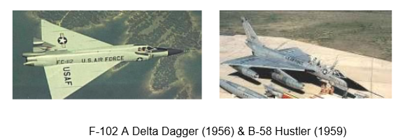
Major fuselage structure changes were forced by the adoption of Whitcomb’s area ruling theory. This involved the incorporation of a gradual change in overall sectional area, in order to reduce the high speed wave drag component. In particular, this requires the reduction in fuselage area where the wing and tail is attached and the narrowing down elsewhere, thereby producing an ideal Sears-Haack body area distribution. This clearly complicated the fuselage structural design and layout processes.
Although the rule still applies, the visible fuselage “waisting” is no longer common; the same effect is now achieved much more subtlely by careful positioning of aircraft components.
Thin Wings
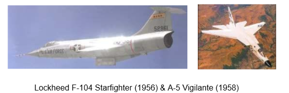
Much thinner wings were needed as aircraft speeds continued to increase during the 1950’s and 60’s, due to aerodynamic considerations (in order to reduce the magnitude of the wave drag due to thickness component). An example includes the Lockheed F-104 Starfighter (1956) with a cruise speed in excess of Mach 2 and a wing t/c ratio of only 3.4%. The adoption of such thin wing sections led to the common use of multi-cell & multi-spar wing structures
Kinetic Heating
Ever-increasing aircraft speeds during the 1950’s led to additional previously unencountered problems in the form of large temperature gradients due to kinetic (aerodynamic) heating. These effects can easily lead to significant thermal stresses and expansion/contraction problems and are big design considerations for supersonic aircraft, e.g. Concorde & B-58 Hustler, where steady- state temperatures of up to 128oC may result for Mach 2 cruise.
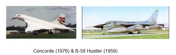
Design solutions include careful material selection (the increased use of high-temperature resistant steel, titanium, etc.) and the incorporation of cut-outs to accommodate thermal expansion limits.
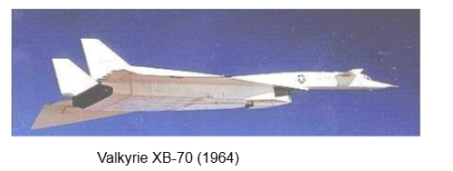
The XB-70 Valkyrie (1964) had even greater problems than Hustler or Concorde due to its even higher speed (Mach 3 cruise). This meant that the aircraft developed maximum local temperatures of about 340oC and average airframe temperature of about 280oC during its flights. The design solution adopted by the structural and materials design engineers incorporated:
- Titanium alloys used for the forward fuselage skin & frames and high-strength H-11 steel used for the stiffeners.
- Brazed stainless steel honeycomb sandwich panels used for the intermediate fuselage & wing.
- Titanium wing spars with sin-wave webs.
- H-11 steel & titanium alloy skin for aft fuselage.
- Welded joints.
Computing Advances
Computers were first used in earnest on aircraft during XB-70 Valkyrie structural development programme. The standard structural hand calculations were heavily supported by extensive use of matrix structural analysis methods on computers. All of the major components were analysed using the force method of linear elasticity with three basic elements (rod, shear panel & built-up beam) used for the modelling. The computer codes used by the engineers were all written in the assembly language and were run on an IBM 7095 mainframe computer.
Finite element analysis was used first of all during the structural support and development phases of the Boeing 747 airliner design programme in the mid 1960’s. The improved analysis capabilities (all later verified through testing) led directly to the evolution of several new design concepts. This included the aeroelastic tailoring of the nacelle & wing/body intersection in order to reduce potential flutter problems and also allowed for the major extensive use of composite materials.
Advanced Materials Technology
Sandwich Structures
This is an ideal way of providing thin sheets with an improved compressive buckling stability. The Mosquito was first to use a form of sandwich construction; its fuselage comprised plywood skins and a balsa core.
The most common form of sandwich material uses a metal (usually aluminium alloy) core of honeycomb cells with thin aluminium alloy facing skins. This type of material has been in common use since the 1960’s for many thin, secondary aircraft sub-structures (e.g. flaps, spoilers, etc.). It has also been used extensively in spacecraft applications.
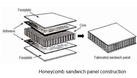
Some of the advantages associated with the use of such honeycomb sandwich materials include: Excellent resistance to buckling & sonic fatigue.High values of specific strength & stiffness.
Disadvantages include: Costly, complicated & lengthy manufacturing processes.The thin, fragile facing skins are susceptible to damage. Field repair is a difficult and specialised task, making it unsuitable for many military applications.Attachment of hardware to the panels difficult, necessitating the use of special “inserts”.
Composites
Composites are simply combinations of two or more different materials, so have been in general use for many years in differing forms:
The DeHavilland Mosquito fuselage used spruce fairings on balsa wood core, as described earlier.
Fibreglass/polyester composites were used for the radomes on many WWII aircraft.
Fibreglass was used for the facing skins on aluminium honeycomb sandwich panels for the Boeing 747 control surfaces (1969).
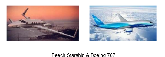
The modern conception of a composite material, however, is that of Carbon-fibre Reinforced Plastics (CFRP), which is becoming increasingly dominant and of widespread use in the aerospace field, e.g. CFRP makes up:26% of the total weight of the AV-8B Harrier (1981) – including the wing, forward fuselage, horizontal tail. 72% of the total weight of a Beech Starship (1986). 12% of the total weight of a Boeing 777 (1995). 50% of the total weight of an Airbus A350XWB (2014).
Other Advanced Materials have been suggested, developed and sometimes tried on aircraft structures, including:
- Aluminium/lithium alloys.
- Aramid/aluminium laminates.
- Metal matrix composites.
- Thermoplastics, etc.
Interested in our Aerospace Engineering Courses?
At iLearn Engineering®, we offer a diverse range of online accredited aerospace engineering courses and qualifications to cater to different academic and career goals. Our aerospace courses are available in varying credit values and levels, ranging from 40 credit Engineering Diplomas to a Bachelor’s equivalent 360 credit International Graduate Diploma.
All Aerospace Engineering Courses
All Aerospace Engineering Diploma Courses can be seen here.
Short Aerospace Courses (40 Credits)
- Diploma in Aerospace Engineering
- Diploma in Aircraft Design
- Diploma in Principles of Flight
- Diploma in Aerospace Structures
- Diploma in Aerodynamics
- Diploma in Aerodynamics, Propulsion and Space
First Year of Undergraduate (Level 4 – 120 Credits)
Higher International Certificate in Aerospace Engineering
Years One and Two of Undergraduate (Level 5 – 240 Credits)
Higher International Diploma in Aerospace Engineering
Degree Equivalent International Graduate Diploma (Level 6 – 360 Credits)
International Graduate Diploma in Aerospace Engineering
Complete Engineering Course Catalogue (all courses)
Alternatively, you can view all our online engineering courses here.
Recent Posts
Understanding Key Performance Indicators in Manufacturing
Understanding Key Performance Indicators in Manufacturing Introduction Key Performance Indicators (KPIs), or sometimes written as Key Performance Measures, are some of the key ‘metrics’ that are used to measure the performance of an industrial system. A good KPI for a manufacturing system should be SMART, that is: Specific – It should measure a specific output […]
Why Lean Manufacturing Matters: Principles of waste
Why Lean Manufacturing Matters: Principles of waste Introduction Lean manufacturing isn’t just a toolkit for improving efficiency, it’s a mindset that reshapes how organisations think about value. At its core, lean focuses on delivering exactly what the customer needs, when they need it, with as little waste as possible. In an increasingly competitive and resource-conscious […]
Breaking Down Aircraft Loads: Types and Real-World Applications
Breaking Down Aircraft Loads: Types and Real-World Applications Introduction An aircraft structure must be designed to withstand a large number of different types of loads. Some of these loads, such as towing, arresting, external stores, and landing gear loads, are applied to the structure at a few discrete locations. These are referred to as point […]