Breaking Down Take-Off: Critical Flight Parameters
Introduction
This blog will summarise the procedures a pilot would follow for take off. We will discuss the necessary considerations for the pilot and factors which affect ground run distance to take off. Firstly, when the pilot calls ‘ready for departure’, there are several possible answers he could get from Air Traffic Control. He may be asked to hold his position, especially if other aircraft are waiting to take off. He may be asked to ‘line up and wait’, which means he can taxi to the start of the runway, and position the aircraft ready to move down the runway, or commence the ‘takeoff roll’, as it is called.
The takeoff roll or ground roll is the portion of the takeoff procedure during which the aeroplane is accelerated from a standstill to an airspeed that provides sufficient lift for it to become airborne. After he has lined up the aircraft with the runway in use, the pilot generally accelerates to full power. The aircraft will try to leave the ground as its speed increases, but the pilot holds it on the ground until it reaches the optimum speed for takeoff. He must not allow it to leave the ground at a slower speed, or there is a danger of a stall.
We can think of the main objective of the take off procedure is to generate sufficient lift to support the aircraft and to generate this lift in the shortest safest distance. Simply increasing the angle of attack, to say 15 degrees at the lowest speed is dangerous, as having left the ground any further increase to the angle of attack to generate lift would cause the aircraft to stall. It is therefore necessary to allow speed to increase beyond the stalling speed before pulling off. The factors that could affect this take off distance include surface roughness of the runway, take off weight of the aircraft, power delivered, lift generated etc.
The use of flaps to increase the lift during take off has to be considered against the increase in drag that deploying them will produce. The increased drag from flap deployment will reduce the acceleration of the aircraft along the runway. However, in most modern commercial aircraft there is always some use of the flaps to generate lift and this is to minimise the final take off velocity required upon take off.
Lift-off is when the wings are lifting the weight of the aeroplane off the surface. At this point, the pilot must ensure that the plane climbs at the correct angle and airspeed. If the plane goes too slowly there is a danger of a stall, but if it goes too fast it will not climb quickly enough for safety. It is essential to climb to a safe height as quickly as possible, since in the unlikely event of engine failure it would be very difficult for the aircraft to land safely if it was too near the ground. Engine failure after takeoff is an emergency which is practised by trainee pilots quite frequently, but it is a difficult procedure.
Take off Performance
An aeroplane is motionless at the end of a runway. This is denoted by location O. The pilot releases the brakes and pushes the throttle to maximum takeoff power, and the aeroplane accelerates down the runway. At some distance from its starting point, the aeroplane lifts into the air. The distance the aeroplane covers along the runway before it lifts into the air is called the ground roll (sg). The total takeoff distance also includes the extra distance covered over the ground after the aeroplane is airborne but before it clears an obstacle of 50 ft for military aircraft and 35 ft for commercial aircraft. This is denoted by sa. The sum of sg and sa is the total takeoff distance.
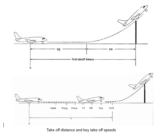
As the aeroplane accelerates from zero velocity, at some point it will reach the stalling velocity VStall. The aeroplane continues to accelerate until it reaches the minimum control speed on the ground, Vmcg. This is the minimum velocity at which enough aerodynamic force can be generated on the vertical fin with rudder deflection while the aeroplane is still rolling along the ground to produce a yawing moment sufficient to counteract that produced when there is an engine failure for a multi engine aircraft.
If the aeroplane were in the air (without the landing gear in contact with the ground), the minimum speed required for yaw control in case of engine failure is slightly greater than Vmcg This velocity is called the minimum control speed in the air, Vmca.
The aeroplane continues to accelerate until it reaches the decision speed, V1. This is the speed at which the pilot can successfully continue takeoff even though an engine failure (in a multi engine aircraft) would occur at this point. If an engine fails before V1 is achieved, the takeoff must be stopped. If an engine fails after V1 is reached, the takeoff has to be completed.
The aeroplane continues to accelerate until the takeoff rotational speed, VR, is achieved. At this velocity, the pilot initiates by elevator deflection a rotation of the aeroplane in order to increase the angle of attack and to overcome the weight. Attention should be paid not to stall.
The angle of attack necessary to overcome the weight may not be achievable because the tail may drag the ground. If the rotation of the aeroplane is limited by ground clearance for the tail, the aeroplane must continue to accelerate while rolling along the ground after rotation is achieved. This speed is called the minimum unstick speed, denoted by Vus.
For increased safety, the angle of attack after rotation is slightly less than the maximum allowable by tail clearance, and the aeroplane continues to accelerate to a slightly higher velocity, called the lift off speed, denoted by VLO. This is the point at which the aeroplane actually lifts off the ground. The total distance covered along the ground to this point is the ground roll sg. Generally VLO = 1.1Vstall
Factors Affecting Ground Run Distance
We will now take a look at the mathematical calculation of the ground roll portion of take off distance, sg. Completing the proof yourself is beyond the scope of this workbook but understanding how the variables and parameters within the equations affect take off distance is important to us. The diagram below shows forces acting on the aircraft during take off. In addition to the familiar forces of thrust, weight, lift, and drag, there is a rolling resistance R, caused by friction between the tires and the ground.
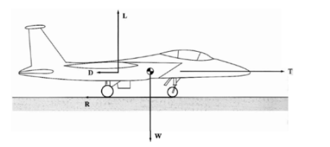
m(dV∞/dt) = T – D – R
and R = μr(W – L)
m(dV∞/dt) = T – D – μr(W – L)
Where all symbols have their normal meaning with the addition of 𝜇, the coefficient of friction of the runway. This parameter decreases with friction on the runway. Some calculus is now involved in order to attain the ground roll portion of take off distance. sg.
ds = ds/dt x dt = V∞dt = V∞ dt / dV∞ x dV∞ = (V∞dV∞)/ dV∞/dt = d(V∞2) / 2(dV∞/dt)
So
ds = m/2( dV∞2) / T-D- μr(W – L)
sg =W/2g ∫0VLO dV∞2 /T-D- μr(W – L)
Integration of the final expression between the stationary speed and lift off speed will give sg. Note that the net force T – D – μr(W – L), does not vary greatly. This gives some justification to assuming that the expression T – D – μr (W – L) is constant up to the point of rotation. If we take this net force to be constant at a value equal to its value at V= 0.7VLo, then:
sg = WV2LO/ 2g [1/ T-D- μr(W – L)]0.7VLO + NVLo
where the term N VLo has been added to account for that part of the ground roll during rotation, as noted earlier. The velocity at liftoff VLO should be no less than 1.1Vstall.
Vstall = √2/ρ∞ x W/S x 1/CLmax
sg = 1.2W/S / gρ∞CLmax [T/W–D/W– μr(W – L)/W]0.7VLO + 1.1N√2/ρ∞ x W/S x 1/CLmax
Assuming that T is much larger than D, neglecting the contribution to sg, from rotation
sg ≈ 1.21W/S / gρ∞CLmax(T/W)
This final simplified equation allows us to make 3 very important observations about how the various parameters affect sg. The design parameters that have an important effect on takeoff ground roll are:
- Wing loading W/S – sg increases with an increase in W/S.
- Thrust-to-weight ratio T/W – sg decreases with an increase in T/W
- Maximum lift coefficient – sg decreases with an increase in CLmax
The ground roll is very sensitive to the weight of the aeroplane via both W/S and T/ W. If the weight is doubled, W/S is doubled and T/ W is halved, leading to a factor-of-4 increase in sg. The ground roll is dependent on the ambient density and increases if density decreases.
Depending on a combination of these factors runways can be constructed up to 4000m. Larger aircraft such as the Airbus A380 would need a maximum runway length of 3000m to reach take off speed. Smaller variants such as the Airbus A320 only need approximately 1800m of runway.
Example: Find the ground roll distance for the following aircraft during take off. The aircraft has a wing loading of 680kgm-2 It has a maximum lift coefficient of 1.2. The thrust to weight ratio during take off is 0.223. Assume a density of 1.225kgm-3 for air at the location of the runway. You may use the following formula to approximate the ground roll:
sg ≈ 1.21W/S / gρ∞CLmaxT/W
Solution: Using the above equation the majority of the work, algebraically, has been completed for us. We simply need to replace wing loading W/S, Lift coefficient, Thrust to weight ratio T/W and density.
sg = 1.21 x 680 / 9.81 x 1.225 x 1.2 x 0.223 = 256m
Finally we can calculate the final part of the take off distance required to clear an obstruction, sa. Below is a sketch of the flight path during take off.
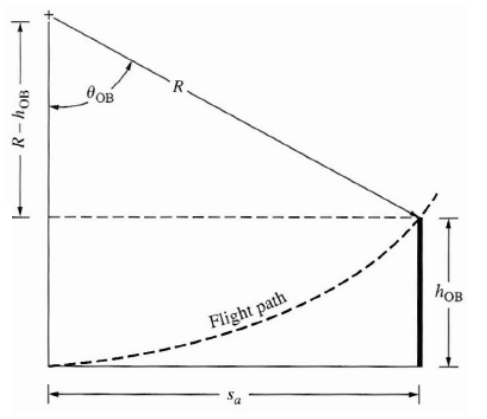
In order to calculate sa we need to make some assumptions. Regulations during take off require the minimum velocity to increase from 1.1 to 1.2 times the stalling speed as it clears the obstacle of height hOB. We can assume velocity to be an average of these values so velocity V = 1.12Vstall For a sufficient margin of safety CL = 0.9CLmax
We will now present the equations used to calculate the missing parameters from the above image. The value used to get R will be taken as 6.96 and is used in the formulas below.
R = V∞/g(n-1) = 6.96V2stall / g
θOB = cos -1 ( 1- hOB/R)
sa = R sin θOB
Example: An aircraft has V = 70m/s, CLmax = 1.25 and it is required to clear a height of 12m. Calculate the final portion of take off distance sa.
Vstall = V/1.15 = 70 / 1.15 = 60.9m/s
R = 6.96 x 60.92 / 9.81 = 2630m
θ = cos -1 ( 1-12/2630) = 5.48º
sa = 2630 sin ( 5.48) = 251m
Interested in our Aerospace Engineering Courses?
At iLearn Engineering®, we offer a diverse range of online accredited aerospace engineering courses and qualifications to cater to different academic and career goals. Our aerospace courses are available in varying credit values and levels, ranging from 40 credit Engineering Diplomas to a Bachelor’s equivalent 360 credit International Graduate Diploma.
All Aerospace Engineering Courses
All Aerospace Engineering Diploma Courses can be seen here.
Short Aerospace Courses (40 Credits)
- Diploma in Aerospace Engineering
- Diploma in Aircraft Design
- Diploma in Principles of Flight
- Diploma in Aerospace Structures
- Diploma in Aerodynamics
- Diploma in Aerodynamics, Propulsion and Space
First Year of Undergraduate (Level 4 – 120 Credits)
Higher International Certificate in Aerospace Engineering
Years One and Two of Undergraduate (Level 5 – 240 Credits)
Higher International Diploma in Aerospace Engineering
Degree Equivalent International Graduate Diploma (Level 6 – 360 Credits)
International Graduate Diploma in Aerospace Engineering
Complete Engineering Course Catalogue (all courses)
Alternatively, you can view all our online engineering courses here.
Recent Posts
Civil Engineering Courses and Diplomas: Topics, Skills and Career Routes
Civil Engineering Courses and Diplomas: Topics, Skills and Career Routes Introduction Civil engineering is the backbone of modern society. From roads and bridges to skyscrapers and water systems, civil engineers design, build, and maintain the infrastructure that keeps the world running. If you’re considering a civil engineering course or diploma, understanding what it covers is […]
What Is a Diploma in Engineering? Courses, Levels and Career Routes Explained
What Is a Diploma in Engineering? Courses, Levels and Career Routes Explained Introduction Engineering shapes the world around us, from the buildings we live in to the technology we use every day. But for many aspiring engineers, the biggest question is not whether to pursue engineering, but how to start. Traditional university degrees are not […]
Engineering Courses: How to Choose the Right Route for Your Career
Engineering Courses: How to Choose the Right Route for Your Career Introduction Choosing an engineering course can feel like standing at the beginning of several different roads, each leading towards a different kind of future. One route may lead into mechanical systems and manufacturing. Another may lead towards aircraft, infrastructure, electronics, computing, renewable energy or […]