The Four Fundamental Forces that Enable Aircraft to Fly
In this article, we will identify the four main forces concerned with aircraft in flight. We will discuss the nature of these forces and deduce mathematical and descriptive definitions. If an aircraft is to be considered in straight and level flight then it will not be gaining altitude, rolling, or yawing. It will be maintaining a constant airspeed, altitude, and heading. If we were to consider the forces acting on the aircraft, it would look something similar to figure 1.

Figure 1
Lift and Drag
Lift and drag are important forces that act upon bodies in a fluid flow, in this case our fluid is air. Firstly, it is important to define these forces, we will then examine the mathematical formulas that describe them. Lift is a force that acts perpendicular to the relative motion of the airflow and acts through the aerodynamic centre of the wing. It is a result of different pressure on two sides of an object, if there is a greater pressure on the underside, lift will be positive and there will exist an upwards force.

Figure 2 demonstrates that the lift is perpendicular to the relative airflow, in straight and level flight. The magnitude of the lift force will depend upon a few key factors and for a wing those factors are the relative velocity between wing and air flow, or air speed, the density of the air, wing area and lift coefficient of the wing. All these values can vary throughout the course of flight. The lift coefficient of an aerofoil depends on several parameters but perhaps the most important is the camber. Lift is always perpendicular to the motion. The position of this force is always at a location called the aerodynamic centre of the wing.
Mathematically we can give the lift force as:

Example 1
If a Boeing 747 has a wing area of 510 m2 and is cruising at 263 m/s, the density of the air is 1.20 kgm-3, and the lift coefficient is 0.6, what is the lift force generated?
Solution:
The most important thing is to check all units are SI, and in this case they are, so we can input them directly into the lift equation above
L= (1/2) (1.2) (263)2 (510) (0.6)
L=12.7 MN
Example 2

Now we will give some thought to the drag force experienced by the aircraft. Drag is a mechanical force that is caused by the difference in velocity between the aircraft and the velocity of the fluid it is moving through (air). For drag to be generated, the solid body must be in contact with the fluid. If there is no fluid, there is no drag. Drag always opposes the motion of the aircraft. The equation that governs drag for a surface moving through a fluid is like that of lift. However, it is slightly more complex and various factors can influence drag, such as:
- Body shape
- Velocity of air
- Turbulence of air
- Surface roughness of body
- Angle of attack of the bod
- Air density
The drag formula is presented below:
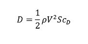
where cD is the drag coefficient.
One of the sources of drag is the skin friction between the molecules of the air and the solid surface of the aircraft. Because the skin friction is an interaction between a solid and a gas, the magnitude of the skin friction depends on properties of both solid and gas. For the solid, a smooth, waxed surface produces less skin friction than a roughened surface. For the gas, the magnitude depends on the viscosity of the air and the relative magnitude of the viscous forces to the motion of the flow.
We can also think of drag as aerodynamic resistance to the motion of the object through the fluid. This source of drag depends on the shape of the aircraft and is called form drag. As air flows around a body, the local velocity and pressure are changed. Since pressure is a measure of the momentum of the gas molecules and a change in momentum produces a force, a varying pressure distribution will produce a force on the body.
There is an additional drag component caused by the generation of lift. Aerodynamicists have named this component the induced drag. It is also called “drag due to lift” because it only occurs on finite, lifting wings. Induced drag occurs because the distribution of lift is not uniform on a wing, but varies from root to tip
Notice that the area (S) given in the drag equation is given as a reference area. The drag depends directly on the size of the body. Since we are dealing with aerodynamic forces, the dependence can be characterised by some area. But which area do we choose? If we think of drag as being caused by friction between the air and the body, a logical choice would be the total surface area of the body. If we think of drag as being a resistance to the flow, a more logical choice would be the frontal area of the body that is perpendicular to the flow direction. And finally, if we want to compare with the lift coefficient, we should use the same wing area used to derive the lift coefficient. Since the drag coefficient is usually determined experimentally by measuring drag and the area and then performing the division to produce the coefficient, we are free to use any area that can be easily measured. If we choose the wing area, rather than the cross-sectional area, the computed coefficient will have a different value. But the drag is the same, and the coefficients are related by the ratio of the areas. In practice, drag coefficients are reported based on a wide variety of object areas. In the report, the aerodynamicist must specify the area used; when using the data, the reader may have to convert the drag coefficient using the ratio of the areas.
Example 3

Thrust and Weight
Thrust is the force which moves an aircraft through the air. Thrust is used to overcome the drag of an aeroplane, and to overcome the weight of a rocket. Thrust is generated by the engines of the aircraft through some kind of propulsion system.
Thrust is a mechanical force, so the propulsion system must be in physical contact with a working fluid to produce thrust. Thrust is generated most often through the reaction of accelerating a mass of gas. Since thrust is a force, it is a vector quantity having both a magnitude and a direction. The engine does work on the gas and accelerates the gas to the rear of the engine; the thrust is generated in the opposite direction from the accelerated gas. The magnitude of the thrust depends on the amount of gas that is accelerated and on the difference in velocity of the gas through the engine.
In an aircraft, the thrust is generated in different ways according to the type of propulsion:
- Turbojet: all the thrust is generated in the form of jet efflux from the rear of the engine. (Now used mostly in military aircraft).
- Turbofan: most of the thrust is generated by a large fan at the front of the engine; a small percentage is generated by jet efflux.
- Turboprop: most of the thrust is generated by the propeller; a small percentage is generated by jet efflux.
- Piston: all the thrust is generated by the propeller.
The Power required to generate thrust depends on a number of factors, but in simple terms it may be said that the power is proportional to the thrust required multiplied by the aircraft speed.
Finally the weight of the aircraft must be considered, it is important to note here that students often confuse weight with mass. The mass of an object is given in kilograms and is a scalar quantity. Weight is a force, measured in newtons, and must be equal to the mass multiplied by the acceleration due to gravity. The direction of the force is always downwards to the centre of the Earth. Just as lift, drag and thrust can all vary throughout the course of a flight so too can the weight. As fuel is burned the mass of the aircraft will decrease significantly.
The thrust can be divided by the weight at specific times to give a useful property called the thrust to weight ratio. This parameter is an important indicator and increases with the aerodynamic performance of an aircraft.
Accredited Aerospace Engineering Courses
This is a small excerpt from iLearn Engineering®‘s suite of accredited Aerospace Engineering courses all of which are available for enrolment 365 days a year.
Why not check out the online engineering short courses specifically in aerospace engineering:
Diploma in Aerospace Structures
Diploma in Principles of Flight
Diploma in Aerodynamics, Propulsion and Space
Alternatively, you can view all our online engineering courses here.
Recent Posts
Civil Engineering Courses and Diplomas: Topics, Skills and Career Routes
Civil Engineering Courses and Diplomas: Topics, Skills and Career Routes Introduction Civil engineering is the backbone of modern society. From roads and bridges to skyscrapers and water systems, civil engineers design, build, and maintain the infrastructure that keeps the world running. If you’re considering a civil engineering course or diploma, understanding what it covers is […]
What Is a Diploma in Engineering? Courses, Levels and Career Routes Explained
What Is a Diploma in Engineering? Courses, Levels and Career Routes Explained Introduction Engineering shapes the world around us, from the buildings we live in to the technology we use every day. But for many aspiring engineers, the biggest question is not whether to pursue engineering, but how to start. Traditional university degrees are not […]
Engineering Courses: How to Choose the Right Route for Your Career
Engineering Courses: How to Choose the Right Route for Your Career Introduction Choosing an engineering course can feel like standing at the beginning of several different roads, each leading towards a different kind of future. One route may lead into mechanical systems and manufacturing. Another may lead towards aircraft, infrastructure, electronics, computing, renewable energy or […]