Why Aircraft Wing Structure Matters More Than You Think
Introduction
Aircraft wings are often admired for their elegant shape and ability to generate lift, but what lies beneath the surface is an intricate structural system that makes safe and efficient flight possible. The wing structure is designed to withstand enormous aerodynamic forces, support the aircraft’s weight, and maintain stability throughout every phase of flight.
Inside a wing, components such as spars, ribs, stringers, and skin work together to form a strong yet lightweight framework. These elements distribute loads, maintain the wing’s aerodynamic shape, and ensure the aircraft can endure turbulence, maneuvering forces, and repeated flight cycles.
Understanding aircraft wing structure is essential not only for aerospace engineers but also for aviation students and maintenance professionals. By exploring how these structural elements interact, we gain insight into why wing design plays such a crucial role in aircraft safety, performance, and overall efficiency.
Specific Roles of Wing Structure
The wing of an aircraft performs several critical structural functions that ensure the aircraft can safely withstand the many forces encountered during flight and ground operations. One of its primary roles is to transmit loads effectively through the structure. The lift generated by the wing is transferred to the fuselage through the wing root via the main spanwise beam, commonly known as the main spar. In addition, inertia loads produced by heavy components such as engines, landing gear, and other mounted systems are carried through the wing structure to this main beam. Aerodynamic forces acting on the aerofoil, including those produced by control surfaces and flaps, are also directed through the wing structure to the main spar, allowing these loads to be distributed safely throughout the aircraft.
The wing structure must also react against several external forces. During landing, significant loads are applied at the wing attachment points, particularly where the landing gear connects to the structure. The wing must be strong enough to absorb and distribute these forces without structural failure. It must also withstand loads transmitted from pylons and external stores, such as fuel tanks or other equipment mounted beneath the wing. Additionally, the wing structure must resist drag forces and any thrust loads that act along the wing during flight.
Beyond carrying and reacting to loads, the wing also serves other essential functions. The internal volume of the wing often provides space for fuel storage, making efficient use of the structure while contributing to aircraft balance and range. At the same time, the wing must maintain sufficient torsional rigidity to ensure structural stiffness and prevent excessive twisting. This rigidity is crucial for meeting aeroelastic requirements and maintaining the wing’s aerodynamic shape and performance throughout the flight envelope.
A conventional aircraft wing structure is made up of several key components that work together to provide strength and maintain the wing’s shape. The main load-carrying members are the spanwise spars or booms, which run along the length of the wing and transfer loads to the fuselage. Ribs, positioned chordwise from the leading edge to the trailing edge, help maintain the aerodynamic shape of the aerofoil and distribute loads across the wing. The outer skin covers the structure, creating a smooth aerodynamic surface while also carrying part of the loads. Stringers run along the span between the spars, reinforcing the skin and preventing buckling. Together, these elements form a strong and lightweight wing structure.
Basic Functions of Wing Structural Members
The structural functions of each of these types of members may be considered independently as:
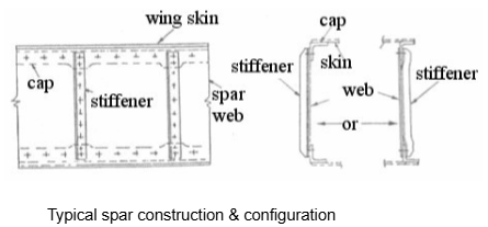
Spars
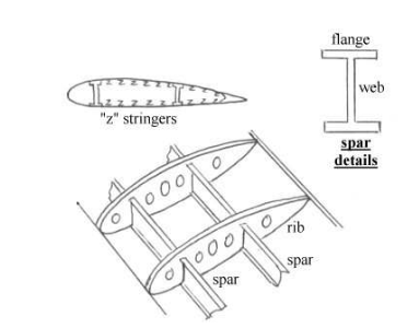
Spars are the main spanwise structural beams of an aircraft wing. They carry and transmit bending and torsional loads to the fuselage and help form a closed-cell structure that resists torsion, shear, and tension. The web of the spar resists shear and torsional loads and stabilises the skin, while the flanges withstand the compressive and tensile forces caused by wing bending.
Skin
The wing skin forms the outer surface of the wing, creating a smooth and impermeable aerodynamic shape that allows efficient airflow during flight. Beyond its aerodynamic role, the skin also contributes to the wing’s structural strength. It helps transmit aerodynamic forces acting on the wing to the internal structure, particularly the ribs and stringers. Working together with the spar webs, the skin also resists shear and torsional loads. In addition, it helps react axial bending loads alongside the stringers, making it an important load-carrying part of the wing structure rather than simply a covering
Stringers
Stringers are longitudinal reinforcing members attached to the wing skin that strengthen the overall structure. Their primary function is to increase the buckling resistance of the skin by dividing large skin panels into smaller sections, which improves their ability to withstand compressive stresses. In addition, stringers help react axial bending loads within the wing, working together with the skin to support the structural loads experienced during flight
Ribs
Ribs are chordwise structural members within the wing that play an important role in maintaining both the shape and strength of the structure. Their primary function is to preserve the aerodynamic profile of the aerofoil, ensuring the wing retains its designed shape during flight. Working together with the wing skin, ribs help resist the distributed aerodynamic pressure loads acting on the surface of the wing.
Ribs also assist in distributing concentrated loads, allowing forces from components such as landing gear attachments, fuel tanks, or access panels to be safely transferred into the surrounding structure. In addition, they help redistribute stress around structural discontinuities, reducing the risk of localised failure. By providing end restraint to the stringers, ribs increase the column buckling strength of these members and also improve the buckling resistance of the skin panels. Together, these functions make ribs a key element in maintaining the structural integrity and aerodynamic efficiency of the aircraft wing.
Wing Box Configurations
Several basic configurations are in use nowadays:
- Mass boom concept
- Box beam (distributed flange) concept – built-up or integral construction
- Multi-spar
- Delta wing
Mass Boom Layout
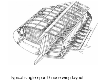
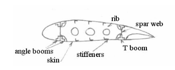
In this design, all of the spanwise bending loads are reacted against by substantial booms or flanges. A two-spar configuration is usually adopted but a single spar “D-nose” configuration is sometimes used on very lightly loaded structures. The outer skins only react against the shear loads, forming a closed-cell structure between the spars. These skins need to be stabilised against buckling due to the applied shear loads; this is done using ribs and a small number of spanwise stiffeners. The diagram shows the cross section of two-spar mass boom wing layout. The resulting layout is simple in terms of design, manufacture and analysis.
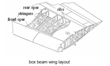
Box Beam or Distributed Flange Layout
This method is more suitable for aircraft wings with medium to high load intensities and differs from the mass boom concept in that the upper and lower skins also contribute to the spanwise bending resistance. Another difference is that the concept incorporates spanwise stringers (usually “z” section) to support the highly-stressed skin panel area. The resultant use of a large number of end-load carrying members improves the overall structural damage tolerance.
Design difficulties include:
- Interactions between the ribs and stringers so that each rib either has to pass below the stringers or the load path must be broken.
- Many joints are present, leading to high structural weight, assembly times, complexity, costs & stress concentration areas.
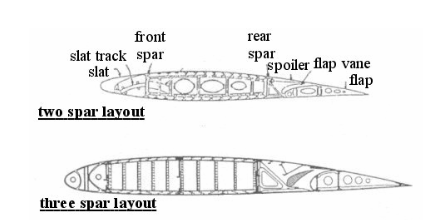
Cross sections of two & three spar box beam wing layouts
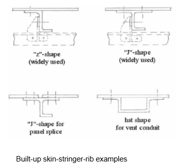
The concept described above is commonly known as a built-up construction method.
Integral construction systems
An alternative is to use a so-called integral construction method. This was initially developed for metal wings, to overcome the inherent drawbacks of separately assembled skin-stringer built-up construction and is very popular nowadays. The concept is simple in that the skin-stringer panels are manufactured together from large billets of metal.
Advantages of the integral construction method over the traditional built-up method include: Simpler construction & assembly. Reduced sealing/jointing problems.
Reduced overall assembly time/costs. Improved possibility to use optimised panel tapering. Disadvantages include: Reduced damage tolerance so that planks are used. Difficult to use on large aircraft panels.
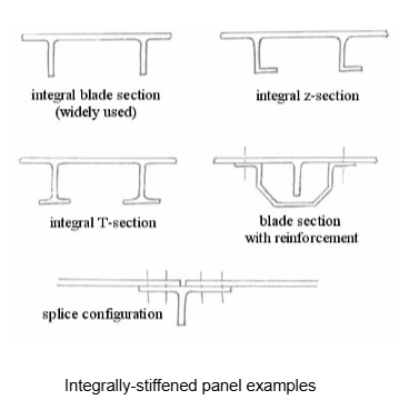
The most efficient use of composites is in an integrally-machined (i.e. moulded) configuration for the wing structure. The skins & webs are then made up with a series of laminations having fibre directions oriented to match the applied loading conditions. Indeed, this is a major advantage associated with the use of composites and directly leads to significant potential for structural mass reductions. There are problems, however, especially regarding increased costs and manufacturing difficulties. In particular, the manufacture of moulded components demands careful planning & control procedures. The use of integrally-machined composite wing structures is becoming more and more common nowadays due to significant weight reduction possibilities and as material and production costs fall and manufacturing experience is gained.
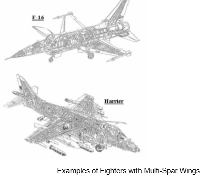
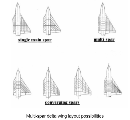
Multi-Spar Layout
These are often used on thin wing (e.g. supersonic) designs, where the usual stringer depth approaches the desired aerofoil section thickness due to aerodynamics (wave drag reduction) considerations. If this is the case, then it is more structurally efficient to dispense with the use of the stringers altogether and replace them with more substantial additional spars. This tends to improve skin buckling stability. These types of wings are usually of low aspect ratio as well as being thin and results in a closely-packed matrix of ribs & spars, sometimes known as an “egg- box” layout. Several layout possibilities exist .
Wing Component Fabrication Methods
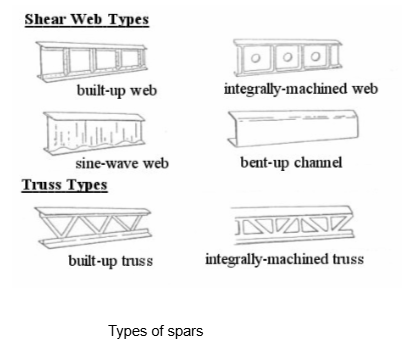
Spars
These usually comprise thin aluminium alloy webs and flanges, sometimes with separate vertical stiffeners riveted to the webs. The flanges are extruded or machined and bolted or riveted onto the webs.
In the case of a two or three spar box beam layout, the front spar should be located as far forward as possible to maximise the wing box size, though this is subject to there being:
- Adequate wing depth for reacting vertical shear loads.
- Adequate nose space for LE devices, de-icing equipment, etc.
This generally results in the front spar being located at 12% to 18% of the chord length.
For a single spar D-nose layout, the spar will usually be located at the maximum thickness position of the aerofoil section (typically between 30% and 40% along the chord length).
For the standard box beam layout, the rear spar will be located as far aft as possible, once again to maximise the wing box size, but positioning will be limited by various space requirements for flaps, control surfaces, spoilers, etc. This usually results in a location somewhere between about 55% and 70% of the chord length. If any intermediate spars are used, they would tend to be spaced uniformly unless there are specific pick-up point requirements.
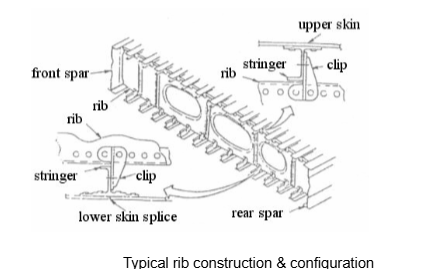
Ribs
For a typical two spar layout, the ribs are usually formed in three parts from sheet metal by the use of presses & dies. Flanges are incorporated around the edges so that they can be riveted to the skin and the spar webs. Cut-outs are necessary around the edges to allow for the stringers to pass through. Lightening holes are usually cut into the rib bodies to reduce the rib weight and also to allow for the passage of control runs, fuel, electrics, etc. Rib bulkheads do not include any lightening holes and are used at fuel tank ends, wing crank locations and attachment support areas.
The ribs should be ideally spaced to ensure adequate overall buckling support to spar flanges. In reality, however, their positioning is also influenced by:
- Facilitating attachment points for control surfaces, flaps, slats, spoiler hinges, powerplants, stores, undercarriage attachments, etc.
- Positions of fuel tank ends, requiring closing ribs.
- A structural need to avoid local shear or compression buckling.
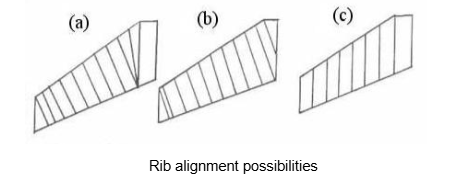
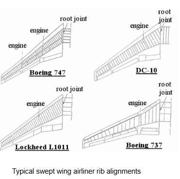
There are several different possibilities regarding the alignment of the ribs on swept-wing aircraft
- (a) Is a hybrid design in which one or more inner ribs are aligned with the main axis while the remainder are aligned perpendicularly to the rear spar.
- (b) Is usually the preferred option but presents several structural problems in the root region.
- (c) Gives good torsional stiffness characteristics but results in heavy ribs and complex connections.
Skin
The skin tends to be riveted to the rib flanges and stringers, using countersunk rivets to reduce drag. It is usually pre-formed at the leading edges, where the curvature is large due to aerodynamic considerations.The wing skin plays an important structural as well as aerodynamic role in an aircraft wing. It transfers the aerodynamic forces acting on the wing surface to the internal structural members, including both the longitudinal components such as spars and stringers and the transverse members like ribs. The skin also develops shear stresses that help the wing react to torsional moments generated during flight. In addition, working together with the longitudinal members, the skin helps resist axial loads and bending forces acting on the wing, contributing significantly to the overall strength and rigidity of the structure.
Interested in our Aerospace Engineering Courses?
At iLearn Engineering®, we offer a diverse range of online accredited aerospace engineering courses and qualifications to cater to different academic and career goals. Our aerospace courses are available in varying credit values and levels, ranging from 40 credit Engineering Diplomas to a Bachelor’s equivalent 360 credit International Graduate Diploma.
All Aerospace Engineering Courses
All Aerospace Engineering Diploma Courses can be seen here.
Short Aerospace Courses (40 Credits)
- Diploma in Aerospace Engineering
- Diploma in Aircraft Design
- Diploma in Principles of Flight
- Diploma in Aerospace Structures
- Diploma in Aerodynamics
- Diploma in Aerodynamics, Propulsion and Space
First Year of Undergraduate Aerospace (Level 4 – 120 Credits)
Higher International Certificate in Aerospace Engineering
Years One and Two of Undergraduate Aerospace (Level 5 – 240 Credits)
Higher International Diploma in Aerospace Engineering
Degree Equivalent International Graduate Diploma in Aerospace Engineering (Level 6 – 360 Credits)
International Graduate Diploma in Aerospace Engineering
Complete Engineering Course Catalogue (all courses)
Alternatively, you can view all our online engineering courses here.
Recent Posts
Understanding Key Performance Indicators in Manufacturing
Understanding Key Performance Indicators in Manufacturing Introduction Key Performance Indicators (KPIs), or sometimes written as Key Performance Measures, are some of the key ‘metrics’ that are used to measure the performance of an industrial system. A good KPI for a manufacturing system should be SMART, that is: Specific – It should measure a specific output […]
How Aircraft Structures Evolved: From Fragile Flyers to Engineering Masterpieces
How Aircraft Structures Evolved: From Fragile Flyers to Engineering Masterpieces Introduction As with all other aspects involved with an aircraft, the structural design and layout has changed markedly over the history of flight, in line with technological advances and new discoveries. This section will highlight some of the more substantial developments made during the history […]
Why Lean Manufacturing Matters: Principles of waste
Why Lean Manufacturing Matters: Principles of waste Introduction Lean manufacturing isn’t just a toolkit for improving efficiency, it’s a mindset that reshapes how organisations think about value. At its core, lean focuses on delivering exactly what the customer needs, when they need it, with as little waste as possible. In an increasingly competitive and resource-conscious […]