What is the Difference between Transformers and Rectifiers in Power Supplies?
In order to answer the question of ‘what is the difference between transformers and rectifiers’, we shall first need to recap on some fundamental background knowledge relating to electromagnetic induction.
Electromagnetic Induction

Electromagnetic induction describes the process of using a moving magnetic field around an electric conductor to create an electromotive force or EMF.
Discovery of electromagnetic induction is accredited to Michael Faraday in 1831 and, independently and almost simultaneously, by Joseph Henry in 1832.

Faraday demonstrated electromagnetic induction using a coil of copper wire wrapped around an iron core, the wire was attached to a galvanometer.
As he moved the magnet towards the coil, the galvanometer displayed a current, the direction of the current changes when the other pole was used.
Many electronic components use this principal, these include transformers, generators, motors and inductors.
In this article we are going to focus on transformers and rectifiers.
Transformers
Transformers consist of two or more coils of wire, wrapped around an iron core that transfer electrical energy as a result of a changing magnetic field.

The iron core serves to magnify the effect of the field produced around the primary coil since iron is a temporary magnet so its poles are easily switched.
As the input voltage is alternating, the magnetic field induced will be changing direction with the same frequency ( 50Hz for mains electricity).
An emf will be produced in the secondary coil due to the change of magnetic flux.
Step up and Step down Transformers
There are two types of transformers, these are the step up and the step down.

From Faraday’s law the induced emf in the primary and secondary coils are:

where N is the number of coils and dΦ/dt is the rate of change of flux. Φ measured in Weber (Wb), and t is the time in seconds (s), V is voltage measured in Volts (V)
Dividing the two equations gives us a direct relationship between the number of coils and the voltages induced:

Efficiency
The following characteristics ensure that transformers are highly efficient:
- Low resistance windings to reduce energy loss through heat.
- Laminated core. Energy loss through heat is reduced.
- Soft iron core used. Easily magnetically ‘switched’.
The efficiency of a transformer is the ratio of power output to power input:

Where Ip is the input current (A), Vp is the input voltage (V), Is is the output current (A) and Vs is the output voltage (V). Efficiency has no units
Some Worked Examples

Rectifiers
Rectifiers are necessary in power transmission as many devices need Direct Current (DC) and not Alternating current (AC).
We will consider some of the main ones below:

Half-wave rectifier
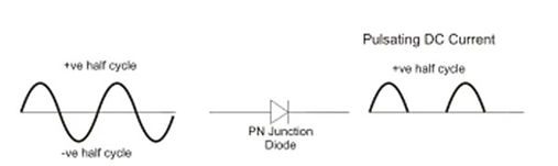
The half-wave rectifier is the simplest form of rectifier as it only allows one half-cycle of an AC voltage waveform to pass, blocking the other half-cycle.
The diagram below illustrates the basic principle of a half-wave rectifier.
When an AC waveform is passed through a half-wave rectifier ( a PN Junction diode) , only half of the AC waveform remains, this can be either the positive or negative half-cycle
We can use a half-wave rectifier to convert the AC input power into DC output power.
When a high AC voltage is applied to the primary side of the step-down transformer a low voltage on the secondary coil will be induced, this voltage passes through a diode which is connected in the secondary circuit.
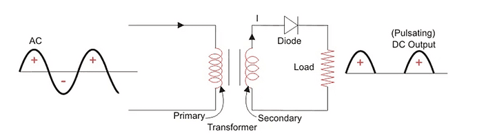
- During the positive half cycle of the AC voltage, the diode will be forward biased and the current flows through the diode.
- During the negative half cycle of the AC voltage, the diode will be reverse biased, and the flow of current will be blocked.
The final output voltage waveform on the secondary side (DC) is shown above.
The secondary transformer coil is now acting as a DC supply, we can simplify the circuit diagram of the half-wave rectifier as:

The graph below shows the input and output waveforms.

The diagram below is shows the cycle if the diode is reversed.
We would now classify the diode as forward biased only when the AC waveform is in its negative half cycle.

Half Wave Rectifier Capacitor Filter
Since DC equipment works best with a constant waveform filters are added to improve the stability, the circuit diagram below shows how a capacitive filter can be used to smooth out a pulsating DC waveform into a more constant DC waveform.
Half wave rectifiers are commonly used in power supplies and rectifiers as the voltage can sometimes be erratic with high fluctuations.
If you connect a smoothing capacitor in parallel with the diode, like this, the resulting waveform will be:
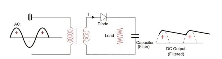
You can see now how much smoother the waveform is. A smoothing capacitor is extremely useful in cases of fluctuating signals that need to be more constant and steady.
Half Wave Rectifier Formula
Even with a filter, the waveform produced will still create a ‘Ripple’, which is the unwanted AC component.
The ripple factor can be calculated using the ratio between VRMS and VDC.
The formula for ripple factor is

Where V RMS is the root mean square of the input voltage (V)
V DC is the output DC voltage (V)
IRMS is the root mean square of the input current (A)
I DC is the output DC current (A)
The ripple factor has no units
The lower the ripple factor, the greater the efficiency
Efficiency of Half Wave Rectifier
Along with the ripple factor, we also need to consider efficiency.
Rectifier efficiency (η) is the ratio between the output DC power and the input AC power.
The formula for the efficiency is equal to:

Where Pdc is the output power (W)
Pac is the input power (W)
The efficiency of a half wave rectifier is equal to 40.6% (i.e. ηmax = 40.6%)
RMS value of Half Wave Rectifier
In engineering we use the RMS value of a half wave rectifier, this can be calculated using the formula below.
If the instantaneous load current is equal to iL = Im sinωt, then the average of load current (IDC) is equal to:

Where Im is the peak instantaneous current across the load (Imax).
Hence the output DC current (IDC) obtained across the load is:
IDC = IMAX / π
where IMAX is the maximum amplitude of the current
Hence the RMS value of the load current (Irms) for a half wave rectifier is:
IRMS = IMAX /2
Peak Inverse Voltage of Half Wave Rectifier
The peak inverse voltage is the maximum voltage that the diode can withstand during reverse bias condition. If a voltage is applied more than this, the diode will be destroyed.
Form Factor of Half Wave Rectifier
Form factor (F.F) is the ratio between RMS value and average value, as shown in the formula below:

The form factor of a half wave rectifier is equal to 1.57 (i.e. F.F= 1.57).
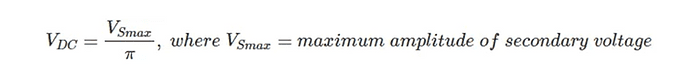
Output DC Voltage
The output voltage (VDC) across the load resistor is denoted by:
Characteristics
| Applications of Half Wave Rectifier | Advantages | Disadvantages |
| Used for rectification | simple ( small number of components | They only allow a half-cycle per wave, power lost due the wasted half-cycle |
| signal demodulation | Cheap upfront costs | Low voltage output |
| signal peak applications | | Output contains a ripple |
As a result of the disadvantages, many systems use a 3 phase half wave rectifier.
3 Phase Half Wave Rectifier
The three-phase half wave rectifier works by converting a three phase AC power supply through three diodes to produce a DC power supply with a lower ripple factor. Since the diodes act as switches there is no way to control the on and off times of these switches.
A typical configuration of a three-phase half wave rectifier supplying a purely resistive load is shown below. Here, each phase of the transformer is considered as an individual alternating source.

If we plot the three-phase voltages we get the graph shown below
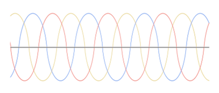
The voltage across the resistive load is shown below. The voltage is shown in black.
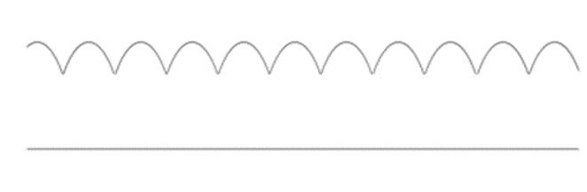
So, we can see from the above figure that the diode D1 conducts when the R phase has a value of the voltage that is higher than the value of the voltage of the other two phases, and this condition begins when the R phase is at a 30º and repeats after every complete cycle.
Here, the waveform of the resulting DC voltage signal is not purely DC as it is not flat, but rather it contains a ripple. And the frequency of the ripple is 3 × 50 = 150 Hz.
By starting with the same calculations that we did for the single phase rectifier, we get the following equations:
The average of the output voltage across the resistive load is given by

Where
RMS value

Voltage ripple factor

The equation above shows that the voltage ripple is significant. This is undesirable as this leads to unnecessary power loss.
DC output power

,
AC input power

Efficiency
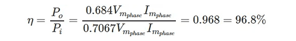
Even though the efficiency of the 3 phase half-wave rectifier is seemingly high, it is still less than the efficiency provided by a 3 phase full wave diode rectifier.
Online Courses and Diplomas in Electrical and Electronic Engineering
Interested in electrical and electronic engineering? Find out more about all the electrical engineering courses we have available by clicking here.
Diploma in Electrical Technology
Diploma in Renewable Energy (Electrical)
Diploma in Electrical and Electronic Engineering
Alternatively, you can view all our online engineering courses here.
Recent Posts
Civil Engineering Courses and Diplomas: Topics, Skills and Career Routes
Civil Engineering Courses and Diplomas: Topics, Skills and Career Routes Introduction Civil engineering is the backbone of modern society. From roads and bridges to skyscrapers and water systems, civil engineers design, build, and maintain the infrastructure that keeps the world running. If you’re considering a civil engineering course or diploma, understanding what it covers is […]
What Is a Diploma in Engineering? Courses, Levels and Career Routes Explained
What Is a Diploma in Engineering? Courses, Levels and Career Routes Explained Introduction Engineering shapes the world around us, from the buildings we live in to the technology we use every day. But for many aspiring engineers, the biggest question is not whether to pursue engineering, but how to start. Traditional university degrees are not […]
Engineering Courses: How to Choose the Right Route for Your Career
Engineering Courses: How to Choose the Right Route for Your Career Introduction Choosing an engineering course can feel like standing at the beginning of several different roads, each leading towards a different kind of future. One route may lead into mechanical systems and manufacturing. Another may lead towards aircraft, infrastructure, electronics, computing, renewable energy or […]