Determine the deflection of cantilever beams with a single load.
If you read our previous article on what is deflection, you’ll have some idea of deflection and it’s magnitude. Now we’re going to investigate how we determine deflection.
What is a cantilever beam?
Cantilever beams are constrained at one end and free at their other end. At the fixed end of the cantilever beam, deflection must be zero. Deflection increases as we move away from the support and the maximum deflection will occur at the free end. The image below shows a cantilever beam in a structure:

Cantilever beams can either be end-loaded or uniformly loaded, and this video can give you some more information on the slope and deflection of a beam along key points.
End-Loaded Cantilever Beams
In end-loaded cantilever beams, the load is applied at a single point on the beam. A cantilever beam with a deflected shape is shown in the first image, while a cantilever beam carrying a point load at its free end is shown in the second image.


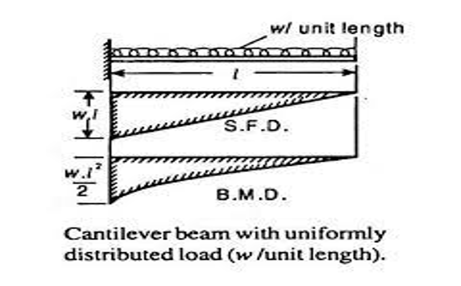
Uniformly-Loaded Cantilever Beams
Uniformly loaded cantilever beams have the force acting uniformly throughout the length of the beam. An example of cantilever beam carrying uniformly distributed load (UDL) is mostly found in balconies. A representation of this type of cantilever beam is shown in the image below:
Standard Data Table for Deflection of Cantilever Beams
Using standard tables is the most practical and fastest approach for calculating the deflection and slope of a beam. For a cantilever beam subjected to a single type of loading, such as point or concentrated load, uniformly distributed load, and couple, deflection and slope can be determined using the formulae in the Table below.

Let’s have a look at an example. Suppose a 3m long cantilever beam is carrying a 25kN point load at its free end. If the moment of inertia of the beam is 108mm4 and the Young’s Modulus is 2.1 105N/mm2, then how would we find the deflection at the free end?
Length of the beam = 3m
Point Load = 25kN = 25000N
Moment of inertia (i) = 108mm4 = 0.0001m4
Young’s Modulus (E) = 2.1 105 N/mm2 = 2.1 1011N/m2
Deflection at the free end = PI33EI = 25000 333 2.1 1011 0.0001 = 0.01071m
Let’s take another example where the beam is 4m long and subjected to a point load of 5kN at the free end. Let’s determine the slope and deflection at the free end, taking flexural stiffness EI as 53.3 MNm2.
Length of beam = 4m
Point load on beam = 5 kN = 5000 N
Flexural stiffness = 53.3 MNm2 = 53.3 106 Nm2
From the Table, the deflection at the free end is given by Pl33EI = 5000 433 53.3 106 = 0.002 m
We’re going to continue our series on deflection with more articles on various calculations with various loads on a beam so stay tuned.
Interested in our courses?
Interested in civil or mechanical engineering? Find out more about all the civil engineering courses we have available by clicking here, and the mechanical engineering courses by clicking here.
Diploma in Mechanical Engineering
Diploma in Mechanical Technology
Diploma in Sustainable Construction
Diploma in Structural Engineering
Diploma in Building and Construction Engineering
Higher International Certificate in Civil Engineering
Higher International Diploma in Civil Engineering
Higher International Diploma in Mechanical Engineering
Higher International Certificate in Mechanical Engineering
Alternatively, you can view all our online engineering courses here.
Recent Posts
Civil Engineering Courses and Diplomas: Topics, Skills and Career Routes
Civil Engineering Courses and Diplomas: Topics, Skills and Career Routes Introduction Civil engineering is the backbone of modern society. From roads and bridges to skyscrapers and water systems, civil engineers design, build, and maintain the infrastructure that keeps the world running. If you’re considering a civil engineering course or diploma, understanding what it covers is […]
What Is a Diploma in Engineering? Courses, Levels and Career Routes Explained
What Is a Diploma in Engineering? Courses, Levels and Career Routes Explained Introduction Engineering shapes the world around us, from the buildings we live in to the technology we use every day. But for many aspiring engineers, the biggest question is not whether to pursue engineering, but how to start. Traditional university degrees are not […]
Engineering Courses: How to Choose the Right Route for Your Career
Engineering Courses: How to Choose the Right Route for Your Career Introduction Choosing an engineering course can feel like standing at the beginning of several different roads, each leading towards a different kind of future. One route may lead into mechanical systems and manufacturing. Another may lead towards aircraft, infrastructure, electronics, computing, renewable energy or […]