How can we analyse undamped vibration problems.
In our previous article on harmonic motion, we looked at how we can analyse problems involving simple harmonic motion, now we’re going to look at solving vibration problems with a single degree of freedom.
Vibration Analysis
In vibration analysis, there are two approaches we are interested in. One is to control undesirable vibration, for example, the loosening of bolts. The other is to enhance desirable vibration, such as mechanical agitators.
To look at either, we need to think about what the cause of vibration is. Any disturbance in a mechanical system in a state of equilibrium results in a vibration response. Disturbance can be from wind gusts on a bridge or aircraft, or periodic impulses from firing events in an internal combustion engine.
Basic concepts
Let’s think about a typical motor vehicle with a wheel and suspension system at each corner. It will look something like this:
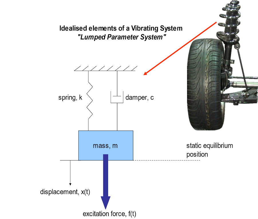
The system is shown as an idealised lumped parameter system. What this means is that all the mass, stiffness, and damping of the real structure have been ‘lumped’ together into idealised lumped parameters.
A lumped parameter system is made up of:
- Mass (kg): the inertia of the real structure is represented and modelled. The idealised mass has a rigid body where work done is stored as kinetic energy – this is where all the mass of the real suspension system is modelled.
- Spring (N/m): this is where the stiffness of the real structure is represented and modelled. The idealised spring has no mass, models an elastic component of the structure, the linear spring obeys Hooke’s Law and spring constant = stiffness = k = force / unit deflection.
- Damper (Ns/m): this is where the damping of the real structure is represented and modelled. The idealised damper has no mass, no elasticity, viscous damping force proportional to velocity, viscous damping coefficient, c = force / unit velocity, work done and energy dissipated as heat (non-conservative system)
Effect of Damping on Response
The response of a system that is undamped typically looks like this:

where the amplitude of the response, y, is A and the time to complete one revolution is the so-called time period, T, and the equation is as we have seen previously, as follows:
y=Asinωt
Now let us look at the response with damping included:

It is clear from the above that damping takes energy out of the system, allowing the mass to decay and rest. The energy is lost as heat in the damper.
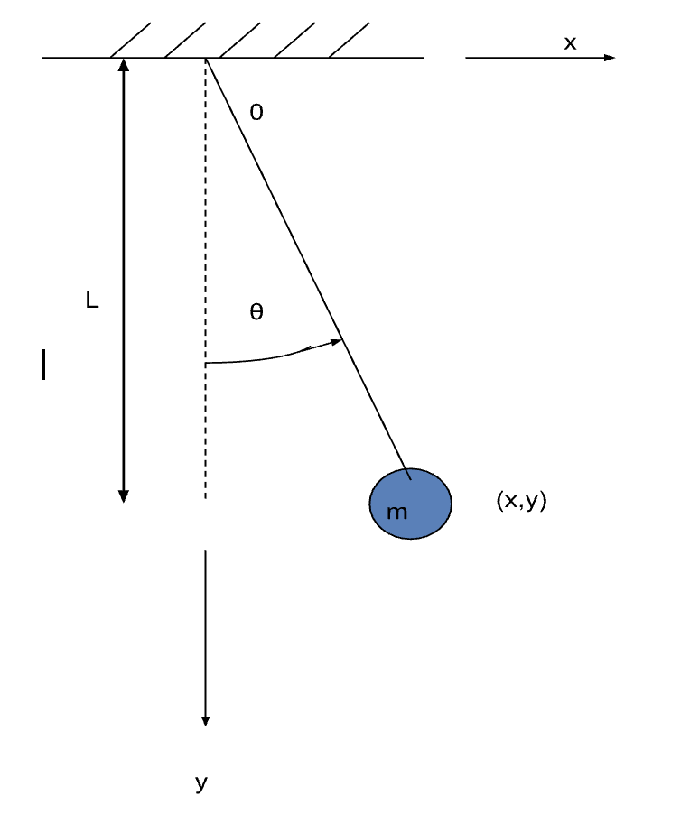
Degrees of Freedom (DOF)
The degrees of freedom of a dynamic model are the number of independent coordinates necessary to describe its motion. The mass on a spring example discussed above is known as a single degree of freedom (SDOF) model because there is only one independent coordinate.
Below, we can see a simple pendulum model. It can be seen that the system is constrained to move in the x-y plane. The configuration can be defined by [x(t) , y(t)] or by θ(t) alone. The (x,y) coordinates are NOT independent as they are related by the following equation of constraint:
x2 + y2 = L2
Therefore, the system is SDOF.
If you find this interesting, make sure to check out our next article on damped vibrations.
Interested in our courses?
Interested in civil or mechanical engineering? Find out more about all the civil engineering courses we have available by clicking here, and the mechanical engineering courses by clicking here.
Diploma in Mechanical Engineering
Diploma in Mechanical Technology
Diploma in Sustainable Construction
Diploma in Structural Engineering
Diploma in Building and Construction Engineering
Higher International Certificate in Civil Engineering
Higher International Diploma in Civil Engineering
Higher International Diploma in Mechanical Engineering
Higher International Certificate in Mechanical Engineering
Alternatively, you can view all our online engineering courses here.
Recent Posts
Understanding Key Performance Indicators in Manufacturing
Understanding Key Performance Indicators in Manufacturing Introduction Key Performance Indicators (KPIs), or sometimes written as Key Performance Measures, are some of the key ‘metrics’ that are used to measure the performance of an industrial system. A good KPI for a manufacturing system should be SMART, that is: Specific – It should measure a specific output […]
How Aircraft Structures Evolved: From Fragile Flyers to Engineering Masterpieces
How Aircraft Structures Evolved: From Fragile Flyers to Engineering Masterpieces Introduction As with all other aspects involved with an aircraft, the structural design and layout has changed markedly over the history of flight, in line with technological advances and new discoveries. This section will highlight some of the more substantial developments made during the history […]
Why Lean Manufacturing Matters: Principles of waste
Why Lean Manufacturing Matters: Principles of waste Introduction Lean manufacturing isn’t just a toolkit for improving efficiency, it’s a mindset that reshapes how organisations think about value. At its core, lean focuses on delivering exactly what the customer needs, when they need it, with as little waste as possible. In an increasingly competitive and resource-conscious […]