Unlocking the Principles of Electromagnetic Induction
Introduction
Electromagnetic induction can be defined as the generation of voltage or a potential difference across a conductor when it is subjected to a changing magnetic field.
This concept of electromagnetic induction was discovered by an English scientist called Michael Faraday in the 1830s. Faraday’s law of electromagnetic induction forms the basis of the concept of electromagnetism that predicts the interaction of a magnetic field with an electric circuit to give an electromotive force (e.m.f.).
This principle is key to the operations of many electrical devices, including transformers, electric generators, motors, inductors etc. For us to properly understand the principles of electromagnetic induction, there is the need to look into the various aspects discussed below.
Definition of terms
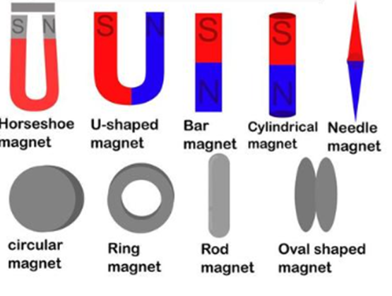
Magnet: This is a piece of iron or other materials which has its component atoms so ordered that the material exhibits properties of magnetism, such as attracting other iron-containing objects or aligning itself in an external magnetic field. It has its origin from Greek (magnetis lithos). It is a material that has the ability to produce (its own) magnetic field. The different types of magnet we have are shown below
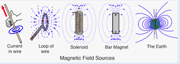
Magnetic field: Magnetic field is the area around a magnet, magnetic object, electric current or an electric charge in which magnetic force is detected or felt. A magnetic field cannot be seen, felt, smelt or heard and therefore is difficult to represent. Magnetic field sources are essentially dipolar in nature, having a north and south magnetic pole.
Coil: A coil in relation to electricity consists of one or more turns of current-carrying wire (which can be cylindrical or approximately circular) designed to generate a magnetic field or to provide electrical resistance or inductance.

Magnetic Flux: It is the number of magnetic field lines which pass through a particular closed surface. It indicates the total magnetic field which passes through that particular surface area. It is represented as Φ or φ. The unit is weber (wb).
Magnetic field lines: These are imaginary lines used in visualising the distribution and density of magnetic fields. They are otherwise called magnetic lines of force or magnetic lines of flux.
They have the following characteristics.
1. The direction of a line of magnetic flux at any point in a non-magnetic medium such as air is that of the north seeking pole of a compass needle placed at that point.
2. Each line of magnetic flux forms a closed loop.
3. Lines of magnetic flux never intercept.
4. Lines of magnetic flux are like structured elastic cords always trying to shorten themselves.
5. Lines of magnetic fluid which are parallel and in the same direction repel one another.
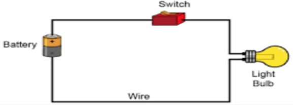
Circuit: A circuit can be defined as a complete circular path through which electric current flows. A simple circuit is made of a current source, conductors and a load. A load is any part of an electrical circuit which converts electric current to light, heat or mechanical motion. In the diagram, the battery is the current source, wire is the conductor and light bulb is the load(converts current to light).
Magnetic circuits: In an electric circuit e.m.f. gives rise to current while in a magnetic circuit magneto motive force (m.m.f.) gives rise to flux. The characteristics of lines of magnetic flux are that each is a closed loop. The complete closed path followed by any group of lines of magnetic flux is referred to as a magnetic circuit. A simple magnetic circuit is shown below
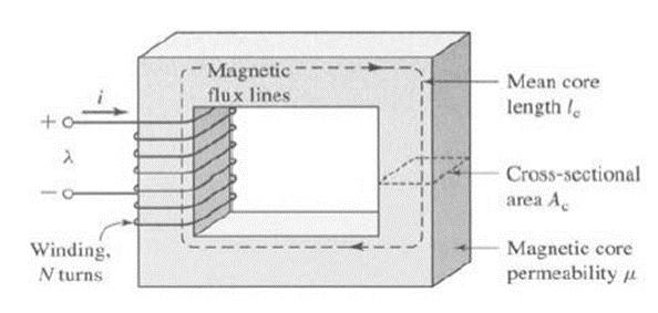
Magnetomotive force (m.m.f): An m.m.f. is caused by current flowing through the coil. Mathematically, m.m.f = NI (Ampere-turns) (AT) N= number of turns of the coil I = Currents through the coil, T is dimensionless.
Identification of the factors necessary for electromagnetic induction to occur
Anytime a conductor moves across a magnetic field in a way that it cuts through the lines of force (or flux), there is a generation of an electromotive force (e.m.f.) in the conductor. Assuming the conductor is part of a closed circuit, then the generated e.m.f. would in turn make an electric current to flow round the circuit. Therefore it is said that an e.m.f. (and hence current) is ‘induced’ in the conductor as a result of the conductor’s movement across the magnetic field. This effect is referred to as ‘electromagnetic induction’.
For this electromagnetic induction process to occur, there are some needed factors required which are:
- Changing Magnetic Field: There must be a change in the magnetic field around the conductor. This change can occur in various ways, such as by moving a magnet near a stationary coil or by changing the current in a nearby coil.
- Conductor: A material through which electricity can flow, such as a wire or coil of wire, must be present. The conductor is where the induced current will flow.
- Relative Motion: The conductor and magnetic field must be in relative motion. This can involve moving the conductor through the magnetic field or varying the strength of the magnetic field while keeping the conductor stationary.
- Magnetic Flux: The concept of magnetic flux (the product of the magnetic field and the area through which it lines) plays a crucial role. A change in the magnetic flux through a loop of wire induces an electromotive force (EMF) in the wire.
- Closed Circuit: For a current to flow, the conductor must form a closed circuit. This means the circuit must be complete so that the induced EMF can drive an electric current through it.
Effect on the conductor by varying the magnetic field, or by moving the conductor
Varying the magnetic field or moving the conductor through a magnetic field induces an e.m.f. and current due to changes in magnetic flux. Faraday’s Law and Lenz’s Law govern these effects, which are the basis for many electrical devices and technologies.
Faraday’s Law of Induction
Faraday’s laws of electromagnetic induction state:
(i) A change in the magnetic flux induces an electromotive force (e.m.f) in the conductor.
(ii) The magnitude of the induced e.m.f. in any circuit is proportional to the rate of change of the magnetic flux linking the circuit.
Lenz’s law
The direction of an induced e.m.f. is always such that it tends to set up a current opposing the motion or the change of flux responsible for inducing that e.m.f.
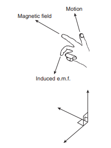
An alternative method to Lenz’s law of determining relative directions is given by Fleming’s Right-hand rule (usually called the geneRator rule), which states: Let the thumb, first finger and second finger of the right hand be extended such that they are all at right angles to each other. If the first finger points in the direction of the magnetic field and the thumb points in the direction of motion of the conductor relative to the magnetic field, then the second finger will point in the direction of the induced e.m.f.
In a generator, conductors forming an electric circuit are made to move through a magnetic field. By Faraday’s law, an e.m.f. is induced in the conductors and thus a source of e.m.f. is created. A generator is used to convert mechanical energy into electrical energy.
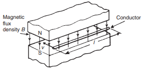
The induced e.m.f. E set up between the ends of the conductor shown is given by:
E = BLv ( measured in volts)
where B is the flux density in teslas, L is the length of conductor in the magnetic field in metres, and v is the velocity of the conductor in metres per second. If the conductor moves at an angle ፀº to the magnetic field then
E = BLv sin ፀ
Mathematically, B = φ/A;
Where φ is the flux in weber and A is the cross-sectional area in m2
Note: In the previous equation E = BLv, it is assumed that ፀ = 90º which means sin 90º = 1
Electromagnetic induction produces an emf
As it has been mentioned before, one of the effects of varying the magnetic field or moving a conductor in a magnetic field is generation of e.m.f. and hence current, we shall look into little illustration to explain how electromagnetic induction generates an e.m.f.
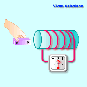
The diagram below shows a coil of wire connected to a centre-zero galvanometer, which is a sensitive ammeter with the zero-current position in the centre of the scale.
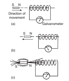
(i) When the magnet is moved at constant speed towards the coil , a deflection is noted on the galvanometer showing that a current has been produced in the coil,( diagram a)
(ii) When the magnet is moved at the same speed as in (i) but away from the coil the same deflection is noted but is in the opposite direction. (diagram b)
(iii) When the magnet is held stationary, even within the coil, no deflection is recorded.
(iv) When the coil is moved at the same speed as in (i) and the magnet held stationary the same galvanometer deflection is noted.
(v) When the relative speed is, say, doubled, the galvanometer deflection is doubled.
(vi) When a stronger magnet is used, a greater galvanometer deflection is noted.
(vii) When the number of turns of wire of the coil is increased, a greater galvanometer deflection is noted.
Diagram c shows the magnetic field associated with the magnet. As the magnet is moved towards the coil, the magnetic flux of the magnet moves across, or cuts, the coil. It is the relative movement of the magnetic flux and the coil that causes an e.m.f. and thus current, to be induced in the coil. This effect is known as electromagnetic induction.
Mathematically,
e = Ndφ / dt
e is the induced voltage (in volts), N is the number of turns in the coil, Φ is the magnetic flux – the amount of magnetic field at a surface (in Webbers) and t is the time (in seconds)
Examples
Example 1: A conductor having a length of 300 mm moves at a uniform speed of 2 m/s at right-angles to a uniform magnetic field of flux density 2.5 T. Calculate the current flowing through the conductor when (i) its ends are open-circuited, (ii) its ends are connected to a load of 20 resistance.
Solution: A conductor moving in a magnetic field has e.m.f. (E) induced in it and hence generates current only when the conductor is part of a closed circuit. (L = 0.3m)
E = BLv
E = 2.5 x 0.3 x 2 = 1.5V
(i) In an open circuit no current flows therefore, there is no current flowing through the conductor in this case.
(ii) when the conductor’s ends are connected to a load of 20 resistance, we have
I = E/R = 1.5/20 = 0.075A
Example 2:A conductor 150 mm long cut a magnetic field which has flux density of 0.3 T. if an e.m.f. of 9 V is induced in the conductor, what is the velocity of the conductor (assuming the conductor, the field and the direction of motion are at right angles to each other)?
Solution
E = BLv
V = E/ BL = 9/(0.3×0.15) = 300m/s
Example 3: A conductor moving with a velocity of 30 m/s at an angle of 30º to a magnetic field produced between two square-faced poles of side length 4 cm. If the flux leaving a pole face is 5μWb, find the magnitude of the induced e.m.f.
Solution
v = 30m/s, L = 4cm = 4/1000 = 0.04m, A = 0.04 x 0.04 = 1.6 x 10⁻³ cm2, φ = 5 x 10⁻⁶ Wb
B = φ/ A = 5 x 10⁻⁶ / 1.6×10-3 = 3.125 mWb/m2
E = BLv sin ፀ
E = 3.125×10-3 x 0.04 x 30 x sin30 = 1.875 x 10⁻³ V = 1.875 mV
Example 4: If a metal airplane has a wingspan of 18 m and flies at 200 km/h, What is the e.m.f. induced between its wing tips assuming the vertical component of the earth’s magnetic field is 80μT.
Solution
B = 80×10-6T, L = 18m, v = 200×1000 / 3600 = 2000/36 m/s
E = BLv
E = 80 x 10-6 x 18 x 2000/36 = 0.08V
Interested in our Electrical Engineering Courses?
At iLearn Engineering®, we offer a diverse range of online accredited electrical engineering courses and qualifications to cater to different academic and career goals. Our courses are available in varying credit values and levels, ranging from 40 credit Engineering Diplomas to a 360 credit International Graduate Diploma.
Short Courses (40 Credits)
A selection of our more popular 40 credit electrical diplomas…
Diploma in Electrical and Electronic Engineering
Diploma in Electrical Technology
Diploma in Renewable Energy (Electrical)
First Year of Undergraduate (Level 4 – 120 Credits)
Higher International Certificate in Electrical and Electronic Engineering
First Two Years of Undergraduate (Level 5 – 240 Credits)
Higher International Diploma in Electrical and Electronic Engineering.
Degree equivalent Graduate Diploma (Level 6 – 360 Credits)
International Graduate Diploma in Electrical and Electronic Engineering
All Electrical and Electronic Courses
You can read more about our selection of accredited online Electrical and Electronic Engineering courses here.
Complete Engineering Course Catalogue (all courses)
Alternatively, you can view all our online engineering courses here.
Recent Posts
Civil Engineering Courses and Diplomas: Topics, Skills and Career Routes
Civil Engineering Courses and Diplomas: Topics, Skills and Career Routes Introduction Civil engineering is the backbone of modern society. From roads and bridges to skyscrapers and water systems, civil engineers design, build, and maintain the infrastructure that keeps the world running. If you’re considering a civil engineering course or diploma, understanding what it covers is […]
What Is a Diploma in Engineering? Courses, Levels and Career Routes Explained
What Is a Diploma in Engineering? Courses, Levels and Career Routes Explained Introduction Engineering shapes the world around us, from the buildings we live in to the technology we use every day. But for many aspiring engineers, the biggest question is not whether to pursue engineering, but how to start. Traditional university degrees are not […]
Engineering Courses: How to Choose the Right Route for Your Career
Engineering Courses: How to Choose the Right Route for Your Career Introduction Choosing an engineering course can feel like standing at the beginning of several different roads, each leading towards a different kind of future. One route may lead into mechanical systems and manufacturing. Another may lead towards aircraft, infrastructure, electronics, computing, renewable energy or […]