Step Up Your Knowledge: Induction Principles in Transformers
Introduction
Transformers are at the heart of modern electrical systems, silently ensuring that the right voltage reaches your home, your phone charger, and even massive industrial machines. But how exactly do these devices step voltage up or down with such efficiency and precision? The answer lies in the fascinating phenomenon of electromagnetic induction, a principle discovered by Michael Faraday that revolutionized electrical engineering.
In this blog, we’ll break down the core principles of electromagnetic induction and show you how they are applied in the design and operation of transformers. Whether you’re a student, an aspiring engineer, or simply curious about how the world stays powered, this is your step-by-step guide to understanding one of the most essential components of electrical technology.
Transformer
A transformer is a device which uses the phenomenon of mutual induction to change the values of alternating voltages and currents. In fact, one of the main advantages of a.c. transmission and distribution is the ease with which an alternating voltage can be increased or decreased by transformers. Losses in transformers are generally low and thus efficiency is high. Being static they have a long life and are very stable. Transformers range in size from the miniature units used in electronic applications to the large power transformers used in power stations; the principle of operation is the same for each. A transformer is represented below as consisting of two electrical circuits linked by a common ferromagnetic core. One coil is termed the primary winding which is connected to the supply of electricity, and the other the secondary winding, which may be connected to a load. A circuit diagram symbol for a transformer is also shown.

Transformer Principle of operation
When the secondary is an open-circuit and an alternating voltage V1 is applied to the primary winding, a small current, called the no-load current I0 flows, which sets up a magnetic flux in the core. This alternating flux links with both primary and secondary coils and induces in them e.m.f.’s of E1 and E2 respectively by mutual induction. The induced e.m.f. E in a coil of N turns is given by:
E = -N dφ / dt
where dφ / dt is the rate of change of flux.
In an ideal transformer, the rate of change of flux is the same for both primary and secondary and thus E1 / N1 = E2 / N2 i.e. the induced e.m.f. per turn is constant. Assuming no losses,
E1 = V1 and E2 = V2
V1/N2 = V2 / N2 or V1/V2 = N1/N2
V1/V2 is called voltage ratio and N1 / N2 is the turns ratio, or the ‘transformation ratio’ of the transformer. If N2 is less than N1 then V2 is less than V1. Hence, the device is termed a step-down transformer. If N2 is greater than N1 then V2 is greater than V1 Hence, the device is termed a step-up transformer. When a load is connected across the secondary winding, current I2 flows. In an ideal transformer losses are neglected and a transformer is considered to be 100 percent efficient.
Input power = output power or V1I1 = V2I2 in an ideal transformer, the primary and secondary ampere-turns are equal.
V1/V2 = I2 /I1
Combining equations gives:
V1/V2 = N1/N2 = I2/I1
The rating of a transformer is stated in terms of the volt-amperes that it can transform without overheating. The transformer rating is either V1I1 or V2I2 where I2 is the full-load secondary current.
Example 1: A transformer has 500 primary turns and 3000 secondary turns. If the primary voltage is 240V, determine the secondary voltage, assuming an ideal transformer.
Solution
For an ideal transformer, voltage ratio = turns ratio
V1/V2 = N1/N2
Therefore,
240/V2 = 500 / 3000
V2 = (240 x 3000) / 500 = 1440V or 1.44kV
Example 2:An ideal transformer has a turns ratio of 8:1 and the primary current is 3A when it is supplied at 240V. Calculate the secondary voltage (V2) and the secondary current (I2)
Solution
A turns ratio of 8:1 means N1 / N2 = 8/1; so a step down transformer.
V1/V2 = N1/N2
or secondary voltage
V2 = N2V2 / N1 = (1 x 240 )/8 = 30V
Also N1 / N2 = I2/I1 I2 = I1 N1 / N2 = (3×8) / 1 = 24V
Transformer no-load phasor diagram
The core flux is common to both primary and secondary windings in a transformer and is thus taken as the reference phasor in a phasor diagram. On no-load the primary winding takes a small no-load current I0 and since, with losses neglected, the primary winding is a pure inductor, this current lags the applied voltage V1 by 90º. In the phasor diagram shown below assuming no losses, current I0 produces the flux and is drawn in phase with the flux. The primary induced e.m.f. E1 is in phase opposition to V1 (by Lenz’s law) and is shown 180º out of phase with V1 and equal in magnitude.
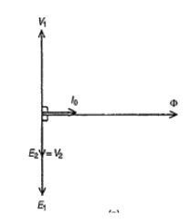
The secondary induced e.m.f. is shown for a 2:1 turn ratio transformer. A no-load phasor diagram for a practical transformer is shown below. If current flows then losses will occur. When losses are considered then the no-load current I0 is the phasor sum of two components.
(i) Im is the magnetising component in phase with the flux, and
(ii) Ic is the core loss component (supplying the hysteresis and eddy current losses).
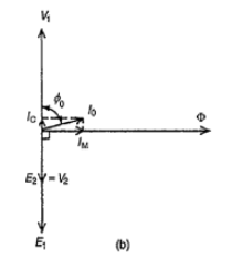
No load current I0 = √Im2 + IC2
Where Im = I0 sin φ0 and Ic = I0cos φ0
Power factor on no-load = cos φ0 = Ic/I0
The total core losses (i.e iron losses) = V1I0 cos φ0
Example: A 2400V/400V single-phase transformer takes a no-load current of 0.5A and the core loss is 400W. Determine the values of the magnetising and core loss components of the no-load current. Draw to scale the no-load phasor diagram for the transformer.
Solution
V1 = 2400V, V2 = 400V, I0 = 0.5A
Core loss (i.e.iron loss) = 400W = V1I0 cos φ0
400 = 2400 x 0.5 x cos φ0
Hence,
cos φ0 = 400 / ( 2400 x 0,5) = 0.33
Φ0 = cos-1(0.33) = 70.53º
The no-load phasor diagram is then shown below:
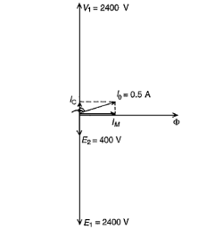
Magnetising component,
Im = I0sin φ0 = 0.5 sin 70.53 = 0.471A
Core loss component,
Ic = I0 cos φ0 = 0.5 cos 70.53 = 0.167A
Interested in our Electrical Engineering Courses?
At iLearn Engineering®, we offer a diverse range of online accredited electrical engineering courses and qualifications to cater to different academic and career goals. Our courses are available in varying credit values and levels, ranging from 40 credit Engineering Diplomas to a 360 credit International Graduate Diploma.
Short Courses (40 Credits)
A selection of our more popular 40 credit electrical diplomas…
Diploma in Electrical and Electronic Engineering
Diploma in Electrical Technology
Diploma in Renewable Energy (Electrical)
First Year of Undergraduate (Level 4 – 120 Credits)
Higher International Certificate in Electrical and Electronic Engineering
First Two Years of Undergraduate (Level 5 – 240 Credits)
Higher International Diploma in Electrical and Electronic Engineering.
Degree equivalent Graduate Diploma (Level 6 – 360 Credits)
International Graduate Diploma in Electrical and Electronic Engineering
All Electrical and Electronic Courses
You can read more about our selection of accredited online Electrical and Electronic Engineering courses here.
Complete Engineering Course Catalogue (all courses)
Alternatively, you can view all our online engineering courses here.
Recent Posts
Civil Engineering Courses and Diplomas: Topics, Skills and Career Routes
Civil Engineering Courses and Diplomas: Topics, Skills and Career Routes Introduction Civil engineering is the backbone of modern society. From roads and bridges to skyscrapers and water systems, civil engineers design, build, and maintain the infrastructure that keeps the world running. If you’re considering a civil engineering course or diploma, understanding what it covers is […]
What Is a Diploma in Engineering? Courses, Levels and Career Routes Explained
What Is a Diploma in Engineering? Courses, Levels and Career Routes Explained Introduction Engineering shapes the world around us, from the buildings we live in to the technology we use every day. But for many aspiring engineers, the biggest question is not whether to pursue engineering, but how to start. Traditional university degrees are not […]
Engineering Courses: How to Choose the Right Route for Your Career
Engineering Courses: How to Choose the Right Route for Your Career Introduction Choosing an engineering course can feel like standing at the beginning of several different roads, each leading towards a different kind of future. One route may lead into mechanical systems and manufacturing. Another may lead towards aircraft, infrastructure, electronics, computing, renewable energy or […]