Transducers Explained: Turning Energy Into Information
Introduction
Transducers are fascinating devices because they act as translators between the physical world and electronic systems. Every time you speak into a microphone, step on a digital scale, or check the temperature on a thermostat, a transducer is quietly doing its job, converting one form of energy into another so it can be measured, processed, or acted upon.
Broadly, transducers can be thought of as either sensors or actuators. Sensors, such as thermocouples or microphones, take in a physical quantity like heat or sound and turn it into an electrical signal. Actuators, on the other hand, do the reverse: they take an electrical signal and transform it into motion, sound, or heat, like the motor in a fan or the speaker in your phone.
Some transducers are active, meaning they generate their own output from the stimulus, such as a piezoelectric crystal that produces voltage when pressed. Others are passive and need an external power source to function, like a resistive temperature detector whose resistance changes with temperature.
The way transducers work also varies. Some rely on resistance, capacitance, or inductance to sense changes, while others use light or even the piezoelectric effect. This diversity allows them to be applied in countless situations, from measuring pressure in an aircraft engine to detecting sound in medical ultrasound imaging.
In everyday life, transducers surround us. They are in the tiny microphones that power voice assistants, the sensors that monitor tire pressure in cars, and the flow meters that help industries manage resources. Whether measuring, sensing, or actuating, transducers are the hidden link that connects our physical world with the digital one.
Electrochemical Transducers
Electrochemical sensors, often called toxic gas sensors, are devices designed to detect and measure the concentration of specific gases by using chemical reactions that produce an electrical current. These sensors are commonly found in applications related to health and safety, where they detect toxic gases like carbon monoxide or measure crucial biological indicators such as blood glucose levels.
How Electrochemical Sensors Work
An electrochemical sensor typically consists of three electrodes:
Working Electrode: Where the primary chemical reaction occurs.
Counter Electrode: Completes the circuit and balances the current flow.
Reference Electrode: Provides a stable reference voltage to enhance measurement accuracy.
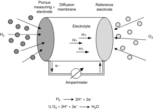
These electrodes sit within a sensor housing containing a liquid electrolyte that facilitates the chemical reactions. A membrane and diffusion-limiting outlet at the top of the housing allow external air to reach the electrolyte, enabling the sensor to interact with the targeted gas in the environment.
When a gas, such as carbon monoxide, interacts with the working electrode oxidation at the working electrode causes electrons to flow through the external circuit toward the counter electrode and reduction at the counter electrode can reverse the electron flow, moving electrons from the counter electrode to the working electrode.
In either case, this movement of electrons generates an electric current proportional to the gas concentration. This current is detected and amplified, then scaled with calibration to provide a reading in engineered units, usually parts per million (PPM) or percentage by volume.
Because electrochemical reactions vary with temperature, temperature compensation is recommended for the most accurate readings. By compensating for temperature fluctuations, the sensor maintains reliability and precision across various environments.
Common Applications of Electrochemical Sensors
Electrochemical sensors are widely used in life-saving devices across medical and environmental applications.
Examples include:
- Breathalysers: Detect alcohol content in a person’s breath, used by law enforcement and healthcare professionals.
- Blood Glucose Sensors: Measure blood glucose levels for diabetes management.
- Respiratory CO₂ Sensors: Monitor carbon dioxide levels in medical ventilators and respiratory care devices.
- Carbon Monoxide (CO) Sensors: Found in home and industrial safety systems to detect toxic levels of carbon monoxide.
- Oxygen Sensors: Used in various medical and industrial applications to measure oxygen levels.
Electrochemical sensors are more widespread than people realise, playing vital roles in health, environmental monitoring, and public safety. Their ability to detect hazardous gases and biological markers helps prevent accidents and save lives, making them indispensable in many fields.
Photoelectric transducers
A Photoelectric Sensor is an optical sensor with an Emitter that sends a light beam and a Receiver that detects it. When an object interrupts or reflects this light, the sensor registers a change in light intensity at the receiver, converting it into an electrical signal. These sensors are widely used in industrial automation, security systems, and packaging, valued for their non-contact detection, speed, and reliability.
Three Types of Photoelectric Sensors
There are three major types of photoelectric sensors: thru-beam, retroreflective, and diffused. Each sensor has its own strengths and can be used in a variety of ways
Thru-Beam: Thru-Beam Sensing (or Opposed Mode Sensing) is a type of photoelectric sensing that uses two separate devices: one with a light emitter and the other with a receiver. The sensor detects objects when something interrupts the light beam between the emitter and receiver.
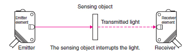
Thru-beam sensors are particularly useful for detecting tiny items that might be hard to sense with other types, fill levels in containers, spliced or overlapped materials, pinpoint an exact location of an object, to detect whether a container holds items or is empty. Effective for objects that block the light beam completely.
Thru-beam sensors are the most accurate among photoelectric sensors, they offer the longest detection range of all photoelectric sensor types and their design allows them to function reliably even when dust or debris is present.
To function properly, thru-beam sensors require the installation of two separate parts: the emitter and the receiver. Proper alignment is crucial for effective sensing.
Thru-beam sensors are ideal for applications needing high precision and reliability, especially in challenging environments.
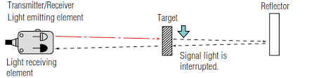
Retroreflective: Retro-Reflective Sensing is a photoelectric sensing method where the light source and receiver are housed together in a single device. The sensor uses a reflector that returns the emitted light back to the receiver. When an object interrupts the light beam, the sensor detects its presence. This variant adds a polarised optical block, which reduces the sensor’s sensitivity to glare or “hot spots” from shiny surfaces on detected objects. Polarised retro-reflective sensors are particularly useful when working with reflective materials.
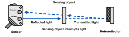
Retro-reflective sensors are well-suited for detecting larger items that easily interrupt the beam, tracking fast-moving items. Ideal for detecting reflective markers or tape. The best option for detecting clear glass or plastic products, where other sensor types might struggle.
Retro-reflective sensors are more affordable than thru-beam sensors, with only slightly less accuracy. They only require wiring on one side, as opposed to thru-beam sensors, which require two-sided wiring. Excellent choice for detecting clear or transparent items, such as glass or plastic.
Diffused: Optical Proximity Sensing, also known as Diffuse Sensing, is a method in which both the light source and receiver are contained in a single housing. The sensor detects objects when the emitted light beam reflects off the target and returns to the receiver. Diffuse sensors are compact because all components are housed together, making them easy to install and cost-effective.
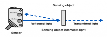
Diffuse sensors are ideal for identifying various items on a moving line; they can detect, though less reliably, translucent items like semi-clear plastic. Suitable for monitoring levels within opaque or semi-transparent containers so are common in packaging and manufacturing. They can detect specific features to assess an object’s orientation and used for quality control, identifying unwanted conditions or defects.
All components are housed together, saving space. Only a single device needs installation, reducing setup complexity and time. Generally more affordable than thru-beam and retro-reflective sensors.
Less Accurate for position detection compared to thru-beam and retro-reflective sensors. Performance may vary with changes in colour, texture, or angle of the detected object as they are sensitive to target characteristics. More susceptible to interference from dirt or dust. They may struggle to detect or misinterpret semi-transparent items.
Diffuse sensors offer a simple, compact, and economical solution for general-purpose automation tasks. However, for applications requiring precise position detection, handling translucent materials, or performance in challenging environments, thru-beam or retro-reflective sensors may be better suited.
Electroacoustic transducers
Acoustic Wave Sensors are devices that use piezoelectric materials to generate and detect acoustic waves. In these sensors, an oscillating electric field is applied to the piezoelectric material, creating a mechanical wave that propagates through the substrate. As the wave travels, it interacts with its environment or the substance being measured. The wave is then converted back to an electrical signal, allowing for measurement and analysis.
Surface Acoustic Wave
Surface Acoustic Wave (SAW) Devices operate at frequencies ranging from MHz to GHz, determined primarily by the design of the interdigital transducer (IDT) and the properties of the piezoelectric material used. The operating frequency, or resonant frequency fres, can be calculated as:
fres = VR / λ
where: VR is the Rayleigh wave velocity (m/s), which depends on the material properties., λ is the wavelength (m) , defined by the periodic spacing of the IDT fingers. fres is the frequency ( Hertz)
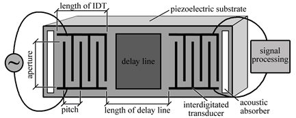
A typical SAW device setup includes:
Two Interdigitated Transducers (IDTs): One IDT acts as the transmitter, generating acoustic waves when an electric signal is applied. The other IDT serves as the receiver, detecting the wave after it propagates across the surface.
Delay Line: The path between the two IDTs, which functions as the sensing area. For sensing applications, this delay line often has a sensor material deposited on it, designed to interact with target analytes (e.g., chemicals) that alter the wave properties.
When an alternating electric signal is applied to the IDT’s interdigitated electrodes, it creates alternating regions of tensile and compressive strain between the electrode fingers due to the piezoelectric effect. This produces a mechanical wave that propagates along the surface of the material. The wave travels from the transmitter IDT across the delay line toward the receiver IDT. Due to the device’s design, only half of the generated wave energy moves in the desired direction toward the output IDT, while the other half propagates in the opposite direction. The delay line, which serves as the sensing region, is sensitive to changes in the surface properties (such as mass loading, temperature, or chemical binding). These interactions can modulate the wave’s velocity and amplitude, which can be detected by the receiver IDT.
SAW devices are particularly useful for chemical sensors, as the delay line can absorb target analytes that change the wave properties. This sensitivity to surface changes makes SAW devices suitable for detecting:chemical and biological substances. Environmental conditions like temperature or humidity.Physical properties such as stress or strain.
SAW devices leverage the piezoelectric effect and the interaction of surface waves with environmental variables, allowing for high-frequency, sensitive measurements across diverse applications.
Mass Sensors
Surface Acoustic Wave Mass Sensors are widely used in applications requiring sensitive detection of target analytes by measuring changes in mass. This type of sensor is commonly applied in gas sensors and biosensors.
A layer of sensor material is deposited along the propagation path between the two interdigitated transducers. When the sensor is exposed to specific analytes, such as a target gas or biological molecules, the active sensing material selectively adsorbs the analyte molecule. The adsorption of analytes increases the mass of the sensing material on the propagation path. This added mass affects the velocity of the surface acoustic wave (SAW), causing it to decrease as it travels from the transmitter IDT to the receiver IDT.The SAW sensor detects this change in wave velocity, which is directly related to the increase in mass, and translates it into an electrical signal.
SAW sensors can detect specific gases by using sensor materials that selectively adsorb gas molecules, enabling precise and sensitive gas monitoring for environmental safety or industrial applications.In biosensing, SAW mass sensors can be used to detect biomolecules such as proteins or pathogens. For example, a bio-sensor might have an antibody-coated sensor material that absorbs specific antigens, causing measurable mass changes.
The SAW sensor’s response to small changes in mass makes it ideal for detecting trace amounts of gases or biomolecules. By choosing appropriate sensor materials, SAW mass sensors can selectively target specific analytes.
Bulk Acoustic Wave: A Bulk Acoustic Wave (BAW) is a type of wave that travels through the interior, or volume, of a piezoelectric material, such as quartz. Because of this, BAW is sometimes referred to as a volume acoustic wave. Unlike Surface Acoustic Waves, which are confined to the surface of the material, BAWs move throughout the entire depth, giving them unique properties and often faster propagation speeds.
BAWs can propagate as either longitudinal waves (where particles move parallel to the wave direction) or shear waves (where particles move perpendicular to the wave direction). Each of these modes has distinct characteristics based on the type of vibration.
In many materials, BAWs travel faster than SAWs. This speed difference arises because SAWs are made up of both longitudinal and shear wave components, which slows their overall propagation speed compared to pure longitudinal or shear waves. The velocity of BAWs depends on the properties of the piezoelectric material they travel through, such as density and elasticity. Due to their stability and high frequency capabilities,
BAWs are widely used in frequency control where Quartz crystal oscillators use BAWs for precise frequency generation, essential in watches, clocks, and telecommunications. BAWs are used to create precise time delays for signal processing, important in communication and radar systems. BAW filters are used in mobile and wireless communication to filter out specific frequencies, enabling clearer signal transmission. Bulk Acoustic Waves are powerful tools in frequency control and signal processing, taking advantage of their faster propagation speeds and stability within piezoelectric materials to provide precise, reliable functionality across various high-tech applications.
Electromagnetic transducer
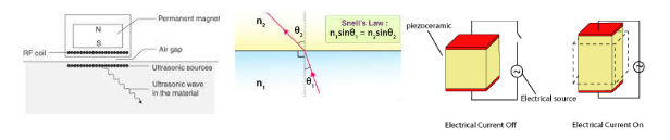
An Electromagnetic Transducer is a self-generating, inductive-type transducer that produces a voltage signal through the relative motion between a conductor and a magnetic field. This type of transducer relies on electromagnetic induction, where a changing magnetic field induces a voltage in a conductor.
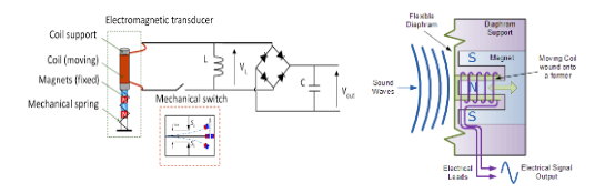
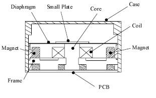
The transducer consists of a coil wound around a permanent magnet core. When an iron or ferromagnetic plate moves relative to the magnet, the magnetic flux field through the coil either expands or collapses, depending on the direction of movement.This change in the magnetic flux induces a voltage in the coil, which can be measured as the transducer’s output.
The voltage generated is directly related to the rate of change in the magnetic flux, which is affected by the speed and direction of the moving ferromagnetic material relative to the magnetic field. Faster movement induces a higher voltage, while slower movement produces a lower voltage.
Electromagnetic transducers are commonly used in applications such as detecting rotational speed in devices like tachometers. Microphones and detecting changes in vibration or position in machinery for predictive maintenance.
Electromagnetic transducers are valued for their simplicity and reliability in generating voltage signals through motion, making them essential in various motion detection and sound applications.
Advantages
Compared to Piezoelectric Transducers, Electromagnetic Transducer Probes offer several distinct advantages, particularly in terms of convenience, versatility, and suitability for certain testing environments.
1. Electromagnetic transducers do not require a couplant
2. Electromagnetic transduction does not require direct contact with the test surface.
3. Since no couplant is required, inspections can be conducted in a dry environment.
4. Piezoelectric transducers require a smooth, machined surface for effective coupling. Electromagnetic transducers, on the other hand, do not have stringent surface smoothness requirements.
5. With piezoelectric transducers, Snell’s law affects wave propagation angles, meaning even slight variations in sensor placement can alter the wave angle significantly. Electromagnetic transducers, however, are less sensitive to deployment angle, making them easier to position accurately.
6. Piezoelectric transducers struggle to generate Shear Horizontal (SH) waves due to the coupling challenges. Electromagnetic transducers, by contrast, can efficiently generate Shear Horizontal bulk and guided waves, which are advantageous for inspecting specific material properties.
Disadvantages
While Electromagnetic Transducers offer several advantages over piezoelectric transducers, they also come with notable limitations. Here are the main disadvantages when compared to Piezoelectric Ultrasonic Transducers:
1.Electromagnetic transducers typically generate weaker signals than piezoelectric transducers.
2.Electromagnetic transducers are generally effective only with metallic or magnetic materials, which limits their use in non-destructive testing of materials like plastics and ceramics.
3. Although small electromagnetic transducers exist, many commonly used models are relatively large.
4.Care must be taken when using electromagnetic transducers around steel or other ferromagnetic materials, as magnet interaction can potentially interfere with the equipment or affect the measurements.
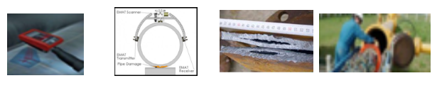
Applications: Electromagnetic Transducer has been used in a broad range of applications and has potential to be used in many other applications. Thickness measurement. flaw detection, plate lamination defects, weld inspection, pipeline in-service inspection, railroad and wheel inspection and material characterization
Electrostatic Transducer
An Electrostatic Transducer operates by utilising two electrodes: a fixed electrode and a movable electrode. These electrodes are charged with opposite polarities, creating an electrostatic field between them.
The fixed and movable electrodes are charged in opposite polarities, creating an attractive electrostatic force between them. When the movable electrode shifts position (due to an external force or vibration), it changes the capacitance between the two electrodes. This capacitance variation is directly related to the displacement or amplitude of the movable electrode’s motion. The change in capacitance induces a corresponding voltage change, which varies proportionally with the motion of the movable electrode. This voltage signal can then be measured, providing information about the electrode’s movement and, by extension, the physical quantity causing the displacement.
Electrostatic transducers are commonly used in microphones, accelerometers and pressure sensors.
This design makes electrostatic transducers highly sensitive to small changes in position, enabling precise measurement of motion, pressure, and sound.
How Electrostatic Speakers Work
An Electrostatic Transducer works by generating sound through the movement of an ultra-light diaphragm that is suspended between two charged stators. This arrangement, assembled like a “sandwich,” consists of three basic components:
Diaphragm: A lightweight plastic film, coated with a conductive material and charged to a fixed positive voltage. The diaphragm is stretched taut between the stators and moves back and forth to produce sound waves.
Stators: These are perforated steel sheets coated with an insulating layer and positioned on either side of the diaphragm. Connected to the audio amplifier through a step-up transformer, the stators receive high-voltage signals of equal strength but opposite polarity.
Spars (Spacers): Non-conductive strips placed width wise along each stator. The spars add structural support to the panel, ensuring that only the diaphragm moves. They also prevent the diaphragm from coming too close to either stator, which is crucial for stable performance.
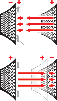
The diaphragm is given a constant positive charge through a high-voltage power supply, creating a stable electrostatic field. The stators are connected to the audio amplifier via a step-up transformer, which increases the amplifier’s output to high-voltage signals of equal strength but opposite polarity. When one stator becomes increasingly positive, the other becomes equally negative. The diaphragm, with its fixed positive charge, is attracted and repelled by the stators depending on their charge polarity.
For example, when the front stator is negative and the back stator is positive, the diaphragm is pulled forward. When the polarity reverses, the diaphragm is pushed back. This oscillating movement, proportional to the audio signal, produces sound waves.
Sound Production: As the charges on the stators vary with the audio signal, the diaphragm’s movement translates the electrical audio signal into physical vibrations, generating sound waves that propagate into the room. The stronger the charge on the stators, the greater the diaphragm displacement, allowing for dynamic sound production.
The spars play a vital role by stiffening the panel to ensure that only the diaphragm moves in response to the audio signal. Keeping the diaphragm at a safe distance from the stators, which avoids distortion and ensures consistent performance.
Conventional speakers and electrostatic speakers differ significantly in how they drive their diaphragms, affecting sound quality, efficiency, and precision.
Conventional Speaker Limitations: In conventional speakers, only a small portion of the diaphragm, often just the centre, is directly driven by the speaker’s motor or coil. The rest of the diaphragm must follow this movement, which poses challenges: The diaphragm must be rigid to avoid flexing, as flexing can create resonances at certain frequencies, leading to distortion and uneven frequency response. For tweeters, especially, the diaphragm must be lightweight to achieve high efficiency and extended high-frequency response. However, balancing lightness with rigidity is challenging, as real materials struggle to meet both requirements simultaneously, resulting in inevitable compromises in sound quality.
Electrostatic Speaker Advantages: Electrostatic speakers, on the other hand, address these issues through a uniformly driven diaphragm:
Uniform Drive: The entire diaphragm surface is driven by the electrostatic field, so the diaphragm doesn’t need to be rigid. This uniform force distribution allows the diaphragm to be extremely light, enabling it to respond quickly and accurately across a wide frequency range.
Reduced Distortion: Electrostatic speakers operate in push-pull mode, where both stators work together to balance forces on the diaphragm. This mode cancels out certain types of distortion, allowing the diaphragm to reproduce even the smallest sonic details with remarkable precision.
Wide Frequency Range: The uniform driving force and light diaphragm allow electrostatic speakers to maintain accuracy over a broad frequency spectrum, from bass to high treble.
Controlled Dispersion: Electrostatic speakers naturally produce a dipolar radiation pattern, meaning they emit sound from both the front and the back of the diaphragm. This design creates a unique sound experience: The dipolar pattern reduces off-axis reflections and enhances sound clarity as you move away from the centerline of the speaker producing clearer Off-Center sound. Controlled Sound Dispersion: This focused dispersion pattern minimises unwanted reflections in the listening space, resulting in a clearer and more immersive listening experience.
Disadvantages
While electrostatic speakers offer remarkable sound quality and precision, several technical challenges have kept them from becoming mainstream, limiting their widespread adoption by speaker manufacturers.
Dynamics and High-Voltage Requirements: Electrostatic speakers require very high electrostatic fields to drive the diaphragm. This requires the stators and diaphragm to be charged to thousands of volts, creating a risk of electrical arcing between the tightly spaced stators and diaphragm. Such arcing can cause electrical discharges that can harm both the speaker components and the amplifier driving them. The high voltage poses an inherent safety risk, requiring extra caution in design and handling.
Bass Response and Dipole Limitations: Electrostatic speakers naturally produce sound in a dipole radiation pattern, meaning they emit sound from both the front and back of the diaphragm. While this design enhances clarity and reduces room reflections, it also results in weaker bass response: At low frequencies, sound waves have long wavelengths that can wrap around the speaker panel. This leads to out-of-phase sound waves from the front and back cancelling each other, reducing bass output. Increasing the panel size can improve bass response by reducing wave cancellation. However, this solution is limited by practical considerations, as larger panels are more cumbersome and difficult to integrate into home audio setups.
Treble Dispersion and “Beaming” Effect: Electrostatic speakers also struggle with treble dispersion at high frequencies: When the wavelength of a sound is shorter than the panel’s width, the sound tends to radiate in a narrow, focused direction, creating a “beaming” effect. This means that high frequencies are projected in a tight, narrow angle, limiting the listening area (or “sweet spot”) where listeners experience the full tonal range. Outside the sweet spot, the sound may lose high-frequency clarity, resulting in a dry, sterile quality. Since electrostatic speakers often require larger panels for bass response and efficiency, high-frequency beaming is a significant challenge, making it difficult to achieve a balanced sound across the room.
While electrostatic speakers offer superb audio precision, designers face challenges related to high-voltage dynamics, limited bass response, and treble beaming. These technical constraints make electrostatics less practical for mass-market speaker systems, as they require careful handling, large panel sizes, and specific room setups to perform optimally. These factors explain why electrostatic speakers remain a niche, high-end product rather than a standard in the speaker industry.
Electromechanical transducers
An Electromechanical Transducer is a device that converts electrical signals into sound waves or sound waves into electrical signals. These transducers are integral to audio devices, where they enable sound production (e.g., loudspeakers) or sound detection (e.g., microphones).
Electromechanical transducers function similarly to loudspeakers:
In devices like speakers, an electric signal drives a diaphragm to create sound waves. The frequency of the sound produced matches the frequency of the input signal, allowing for accurate audio reproduction.
In devices like microphones, sound waves cause a diaphragm to vibrate, which in turn generates an electrical signal that corresponds to the original sound wave.
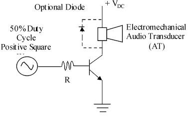
Audio Indicators with Built-in Oscillators
Some electromechanical audio indicators have built-in oscillators and wave shaping networks. When a DC voltage is applied, these devices produce sounds such as a
siren which has a rising and falling pitch that simulates a siren, a sound that alternates between on and off, creating a pulsating effect or a steady, unbroken tone.
These audio indicators are widely used in alarm systems, timers, and other devices requiring auditory alerts due to their ability to generate distinct sounds for various signals
Drive Circuits For Electromagnetic Transducers: Electromechanical audio indicators only require a DC voltage supply to turn the device on. Audio transducers, on the other hand, require a tone generating drive circuit to operate. The diagram shows an example.
Microphones
To evaluate different types of microphones for specific uses, we should consider their frequency response linearity, directional characteristics, durability, and cost:
Linearity: This refers to a microphone’s ability to produce an electrical output proportional to the amplitude of the sound input across the frequency range. A more linear (or flatter) microphone is often preferable for high-quality musical reproduction, where it needs to capture both low and high frequencies accurately. For voice applications, the required frequency range is narrower.
Directivity: Microphones vary in their directional characteristics:
- Omnidirectional microphones capture sound from all directions equally, making them ideal for recording ambient sound or for situations where sound from various directions is desired.
- Cardioid microphones are a type of directional microphone with a heart-shaped sensitivity pattern, making them effective for focusing on sound sources from the front while reducing noise from the sides and back.
- Shotgun microphones have a highly focused forward response, often used in film, TV, and fieldwork to capture sound from a specific direction while minimising background noise.
- Parabolic microphones use a parabolic reflector to amplify weak sounds from a distance, useful in sports or nature recording where sounds from a specific direction need amplification, like capturing bird calls or sports play sounds
Interested in our Electrical Engineering Courses?
At iLearn Engineering®, we offer a diverse range of online accredited engineering courses and qualifications to cater to different academic and career goals. Our courses are available in varying credit values and levels, ranging from 40 credit Engineering Diplomas to a 360 credit International Graduate Diploma.
Short Courses (40 Credits)
A selection of our more popular 40 credit electrical diplomas…
Diploma in Electrical and Electronic Engineering
Diploma in Electrical Technology
Diploma in Renewable Energy (Electrical)
First Year of Undergraduate Electrical (Level 4 – 120 Credits)
Higher International Certificate in Electrical and Electronic Engineering
First Two Years of Undergraduate Electrical (Level 5 – 240 Credits)
Higher International Diploma in Electrical and Electronic Engineering.
Degree equivalent Graduate Diploma Electrical (Level 6 – 360 Credits)
International Graduate Diploma in Electrical and Electronic Engineering
All Electrical and Electronic Courses
You can read more about our selection of accredited online Electrical and Electronic Engineering courses here.
Complete Engineering Course Catalogue (all courses including industrial, mechanical and computer engineering)
Alternatively, you can view all our online engineering courses here.
Recent Posts
Civil Engineering Courses and Diplomas: Topics, Skills and Career Routes
Civil Engineering Courses and Diplomas: Topics, Skills and Career Routes Introduction Civil engineering is the backbone of modern society. From roads and bridges to skyscrapers and water systems, civil engineers design, build, and maintain the infrastructure that keeps the world running. If you’re considering a civil engineering course or diploma, understanding what it covers is […]
What Is a Diploma in Engineering? Courses, Levels and Career Routes Explained
What Is a Diploma in Engineering? Courses, Levels and Career Routes Explained Introduction Engineering shapes the world around us, from the buildings we live in to the technology we use every day. But for many aspiring engineers, the biggest question is not whether to pursue engineering, but how to start. Traditional university degrees are not […]
Engineering Courses: How to Choose the Right Route for Your Career
Engineering Courses: How to Choose the Right Route for Your Career Introduction Choosing an engineering course can feel like standing at the beginning of several different roads, each leading towards a different kind of future. One route may lead into mechanical systems and manufacturing. Another may lead towards aircraft, infrastructure, electronics, computing, renewable energy or […]