EMF Equation of a Transformer and Voltage Transformation Ratio Explained
Introduction
Transformers are fundamental devices in electrical power systems, enabling efficient transfer of energy by stepping voltage levels up or down as needed. In this post, we’ll break down the EMF (electromotive force) equation of a transformer and explain the voltage transformation ratio in a clear, accessible way. Whether you’re refreshing your engineering fundamentals or learning the theory for the first time, by the end you’ll understand:
- How induced EMF depends on magnetic flux, frequency, and turns ratio
- Why the turns ratio determines the relationship between primary and secondary voltages
- How these principles apply in real-world transformer design and applications
In a transformer, an alternating current (AC) source is applied to the primary winding, creating a magnetising current. This current produces alternating flux in the transformer’s core, which links with the secondary winding. Through mutual induction, this alternating flux induces an EMF in the secondary winding.
The magnitude of this induced EMF can be calculated using the EMF equation of the transformer:
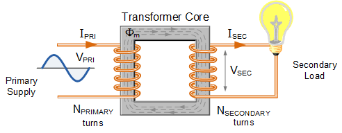
E1 / N1 = E2 / N2 = 4.44 fΦm
or E = 4.44NfΦm ( for a single coil)
where: N1 = Number of turns in primary winding, N2 = Number of turns in secondary winding, Φm = Maximum flux in the core (in Wb) = (Bm x A), f = frequency of the AC supply (in Hz)
This is called the emf equation of the transformer, which shows, emf / number of turns is same for both primary and secondary winding.
For an ideal transformer on no load, E1 = V1 and E2 = V2 .
where, V1 = supply voltage of primary winding (V)
V2 = terminal voltage of secondary winding (V)
Examples
Example 1:
If a transformer has an input voltage of 240V, primary coils = 600, and secondary coils are 40.What is the output voltage?
V1 / N1 = V2 /N2
240V/600 = V2 /40, V2 = 16V
Example 2:
What is the peak flux if N1 = 480, E1 = 2200V and frequency is 50Hz
Solution:
Using the emf equation of a transformer
E1 = 4.44fΦm N1
Φm = 2200/ (4.44 x 50 x 480)
Φm = 0.0206Wb
Example 3.
A transformer has 500 turns on the primary winding and 40 turns on the secondary winding. The primary is connected to a 3000 volt, 50 Hz supply.
Calculate:the maximum core flux
Solution:
E1 = 4.44fΦm N1
Φm = 3000/ (4.44 x 50 x 500)
Φm = 0.027Wb
Voltage Transformation Ratio (K)
From the previous equation we can rewrite it as
E1 / N1 = E2 / N2 = K
Where, K = constant
This constant K is known as voltage transformation ratio.
- If N2 > N1, i.e. K > 1, then the transformer is called step-up transformer.
- If N2 < N1, i.e. K < 1, then the transformer is called step-down transformer.
Transformer – Losses And Efficiency
Transformer Losses refer to the difference between input power and output power and are purely electrical due to the transformer’s static nature. Transformers experience no mechanical losses (like windage or friction losses) since they have no moving parts.
The primary types of losses in a transformer are:
Iron Losses: These occur in the core and include hysteresis Loss due to the magnetising and demagnetizing of the core and Eddy Current Loss caused by circulating currents within the core.
Copper Losses: These are resistive losses in the windings, dependent on the load current, often referred to as I²R losses, these losses are similar to those in a DC machine but exclude mechanical losses, making transformers highly efficient.
Core Losses Or Iron Losses: Eddy current loss and hysteresis loss depend upon the magnetic properties of the material used for the construction of core. Hence these losses are also known as core losses or iron losses.
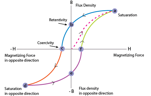
Hysteresis loss in transformer:
Hysteresis loss in a transformer is caused by the reversal of magnetization in the core as the magnetic field changes direction.
This loss depends on:
The volume and grade of the core material (iron), as different materials have varying magnetic properties.
The frequency of magnetic reversals (AC frequency), since higher frequency increases the number of magnetization cycles per second.
The flux density in the core, where higher flux density increases the energy required for each cycle of magnetization.
Reducing hysteresis loss often involves selecting high-grade core materials that minimise energy loss during these magnetic reversals.
It can be given by, Steinmetz formula:
Wh= ηBmax1.6 fV (watts)
where, η = Steinmetz hysteresis constant, V = volume of the core in m3
Eddy current loss in a transformer occurs when the alternating current in the primary winding creates an alternating magnetic flux. While this flux induces an EMF in the secondary winding, some of it also links with other conducting parts of the transformer, such as the steel core or iron body. This induces an EMF in these conductive parts, generating small circulating currents, known as eddy currents.
These eddy currents cause energy dissipation in the form of heat, leading to eddy current loss. To minimise these losses, transformer cores are typically laminated, reducing the paths available for eddy currents and thus decreasing the associated heat and energy loss.
Copper Loss In Transformer:
Arises from the ohmic resistance in the windings.
It is calculated as:
Primary winding copper loss: I12R1 where I1 is the current in the primary winding, and R1 is the primary winding resistance.
Secondary winding copper loss: I22R2 , where I2 is the current in the secondary winding, and R2 is the secondary winding resistance.
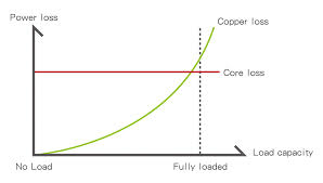
Since copper loss is proportional to the square of the current I2, and current varies with the load, copper loss in the transformer also varies with load. As load increases, copper loss increases, affecting the transformer’s efficiency at different load levels
Efficiency Of Transformer
Just like any other electrical machine, efficiency of a transformer can be defined as the output power divided by the input power. That is
efficiency = output / input
efficiency = (input – losses) / input = 1 – (losses / input).
Transformers are extremely efficient devices, with full-load efficiency typically ranging between 95% and 98.5%. Due to the minimal difference between input and output power, calculating transformer efficiency directly using output/input is often impractical. Instead, a more effective method is to calculate efficiency using the formula:
This approach considers both copper losses (I²R losses in the windings) and iron losses (core losses due to hysteresis and eddy currents), allowing for a more accurate measure of transformer efficiency.
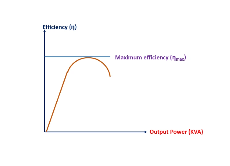
Condition For Maximum Efficiency
We can derive the relationship between Copper loss and Iron loss, Let:
Copper loss = I12R1
Iron loss = Wi
Efficiency = 1 – losses / input = 1 – I12R1 + W1 / V1I1cos Φ1
η = 1 – I1R1 / V1cos Φ1 – W1 / V1I1cos Φ1
Differentiating the equation with respect to I1
dη / dI1 = 0 – R1 / V1cosΦ1 + W1 / V1I12cos Φ1
η will be a maximum at dη/dI1 = 0
So efficiency will be a maximum at
R1 / V1cosΦ1 = W1 / V1I12cos Φ1
I12R1 / V1I12cosΦ1 + W1 / V1I12cos Φ1
I12R1 = W1
Hence, efficiency of a transformer will be maximum when copper loss and iron losses are equal.
That is Copper loss = Iron loss.
All Day Efficiency Of Transformer
Ordinary efficiency = output ( in Watts) / input ( in Watts)
For certain transformers, like distribution transformers, ordinary efficiency (output/input) is not the best measure of performance. Distribution transformers often have their primaries energised continuously, while their secondaries supply load intermittently, typically experiencing light or no load during the day, with peak usage during evening hours.
In these situations:
Core losses(which occur continuously when the transformer is energised) become the main source of loss at low or no load, while copper losses are minimal or absent.
Copper losses become significant only during periods of high load, such as in the evening.
All day efficiency = output in kWh / input in kWh ( for 24 hours)
Therefore, the performance of such transformers is better assessed by the energy consumed over a full day, as this metric considers the continuous core losses and the variable copper losses throughout the daily load cycle. This approach provides a more accurate measure of efficiency for transformers with fluctuating load profiles.
Example 1
A 200 kVA single-phase transformer is in circuit throughout 24 hours. For 8 hours in a day, the load is 150 kW at 0.8 power factor lagging and for 7 hours, the load is 90 kW at 0.9 power factor. Remaining time or the rest period, it is at no-load condition. Full-load Cu loss is 4 kW and the iron loss is 1.8 kW. Calculate the all-day efficiency of the transformer.
Solution
Full-load output = 200 kVA, Full-load Cu loss = 4 kW, Iron loss = 1.8 kW.
Copper loss for 24 hours = (150 / (0.9/200)2 x 4 x 8 + (90 / (1/200)2 x 4 x 7 = 27.89kWh
Iron loss for 24 hours = 1.8 x 24 = 43.2kWh
All day output = (150 x 8) + (90×7) = 1830kWh
All day input = 1830 + 27.89 + 43.2 = 1901.09kWh
All day efficiency, η = all day output / all day input
η = 1830 / 1901.09 = 0.9625 or 96.26%
Interested in our Electrical Engineering Courses?
At iLearn Engineering®, we offer a diverse range of online accredited electrical engineering courses and qualifications to cater to different academic and career goals. Our courses are available in varying credit values and levels, ranging from 40 credit Engineering Diplomas to a 360 credit International Graduate Diploma.
Short Courses (40 Credits)
A selection of our more popular 40 credit electrical diplomas…
Diploma in Electrical and Electronic Engineering
Diploma in Electrical Technology
Diploma in Renewable Energy (Electrical)
First Year of Undergraduate (Level 4 – 120 Credits)
Higher International Certificate in Electrical and Electronic Engineering
First Two Years of Undergraduate (Level 5 – 240 Credits)
Higher International Diploma in Electrical and Electronic Engineering.
Degree equivalent Graduate Diploma (Level 6 – 360 Credits)
International Graduate Diploma in Electrical and Electronic Engineering
All Electrical and Electronic Courses
You can read more about our selection of accredited online Electrical and Electronic Engineering courses here.
Complete Engineering Course Catalogue (all courses)
Alternatively, you can view all our online engineering courses here.
Recent Posts
Understanding Key Performance Indicators in Manufacturing
Understanding Key Performance Indicators in Manufacturing Introduction Key Performance Indicators (KPIs), or sometimes written as Key Performance Measures, are some of the key ‘metrics’ that are used to measure the performance of an industrial system. A good KPI for a manufacturing system should be SMART, that is: Specific – It should measure a specific output […]
How Aircraft Structures Evolved: From Fragile Flyers to Engineering Masterpieces
How Aircraft Structures Evolved: From Fragile Flyers to Engineering Masterpieces Introduction As with all other aspects involved with an aircraft, the structural design and layout has changed markedly over the history of flight, in line with technological advances and new discoveries. This section will highlight some of the more substantial developments made during the history […]
Why Lean Manufacturing Matters: Principles of waste
Why Lean Manufacturing Matters: Principles of waste Introduction Lean manufacturing isn’t just a toolkit for improving efficiency, it’s a mindset that reshapes how organisations think about value. At its core, lean focuses on delivering exactly what the customer needs, when they need it, with as little waste as possible. In an increasingly competitive and resource-conscious […]