Exploring Induction and Synchronous Motors in Modern Engineering
Introduction
Electric motors are essential machines that convert electrical energy into mechanical energy, powering everything from household appliances to large industrial systems. Among the most widely used types are induction motors and synchronous motors. Both play a critical role in modern engineering, yet they differ in their design, working principles, and applications.In this blog, we will explore the general construction, operation, and practical uses of induction and synchronous motors. By the end, you will have a clear understanding of how each motor functions, where they are applied, and why engineers choose one over the other in different scenarios.
Induction Motor: Working Principle, Types, & Definition
An induction motor is a type of electric motor that operates based on the principle of electromagnetic induction. It is one of the most commonly used motors in industrial and domestic applications due to its robustness, simplicity, and reliability. The induction motor operates on Faraday’s Law of Electromagnetic Induction and Lenz’s Law.
Stator Field Generation: The stator (stationary part) of the motor contains coils connected to an alternating current (AC) power supply. When AC flows through these coils, it produces a rotating magnetic field (RMF) in the stator.
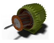
Induction in the Rotor: The rotor (rotating part) is usually made of conductive bars (as in a squirrel-cage rotor) or wound with coils (as in a wound rotor). As the stator’s magnetic field rotates, it cuts through the rotor conductors. According to Faraday’s Law, this induces a current in the rotor.
Air Gap: A small gap between the stator and rotor where electromagnetic interaction occurs.
Torque Production: The induced current in the rotor interacts with the stator’s magnetic field, generating a force (per Lenz’s Law) that causes the rotor to turn in the same direction as the stator’s rotating magnetic field. The rotor always lags behind the rotating magnetic field to maintain relative motion for induction. This difference in speed is called slip.
Types of Induction Motors
Single-Phase Induction Motor: Powered by single-phase AC and common in household appliances like fans, pumps, and refrigerators.
Three-Phase Induction Motor: Powered by three-phase AC, which produces a smoother rotating magnetic field. Widely used in industrial applications for machines, conveyors, and compressors.
Advantages: Simple Construction so no brushes or commutators, leading to low maintenance. Durability so they can operate under harsh conditions. Economical compared to other motor types. Long lifespan and robust design. Self-Starting: Particularly true for three-phase motors.
Disadvantages: Speed Control is difficult compared to DC motors. Power Factor: Operates at a lagging power factor, especially at light loads. Slightly lower efficiency than synchronous motors at certain conditions.
Applications: Industrial Machines: Lathes, mills, and conveyors. HVAC Systems: Compressors, fans, and blowers. Home Appliances: Washing machines, air conditioners, and refrigerators. Pumps and Fans: Agricultural and commercial pumping systems.
Comparison to Other Motors
Stepper Motor: Precise position control but lower power.
Synchronous Motor: No slip, operates at constant speed, but requires an external DC excitation.
DC Motor: Offers easier speed control but requires brushes and commutators, making maintenance higher.
Why is Three Phase Induction Motor Self Starting?
A three-phase induction motor is self-starting due to the unique nature of its stator and the rotating magnetic field (RMF) it produces when connected to a three-phase AC supply.
When a three-phase AC supply is applied to the stator windings, each winding receives current with a phase difference of 120º.
This creates three alternating magnetic fields in the stator, which combine to produce a single rotating magnetic field.
The RMF rotates at the synchronous speed, determined by the supply frequency and the number of poles in the stator.
Synchronous Speed (Ns) Formula:
Ns = 120f / P
Where: f = Supply frequency (Hz) P = Number of poles
Interaction with Rotor: The rotating magnetic field induces a current in the rotor (due to electromagnetic induction, as per Faraday’s Law). This induced current in the rotor generates its own magnetic field. According to Lenz’s Law, the rotor tries to oppose the relative motion between itself and the RMF. As a result, the rotor begins to rotate in the same direction as the RMF.
No External Starting Mechanism Required: Unlike a single-phase induction motor, where the magnetic field is pulsating and not inherently rotating, the three-phase induction motor’s stator inherently creates a rotating magnetic field. This eliminates the need for external starting devices and additional components like starting windings or capacitors. The torque produced is sufficient to overcome the initial inertia of the rotor, making the motor self-starting.
Advantages of Self-Starting Nature: Simple Design so no additional starting mechanisms are needed. Reliable Operation as fewer components reduce the chance of failure. Cost-Effective as it eliminates the need for extra equipment like starting capacitors or auxiliary windings.
Why Single-Phase Motors Are Not Self-Starting?
In contrast, single-phase motors produce a pulsating magnetic field rather than a rotating one, which cannot initiate rotor motion on its own. Single-phase motors require external methods, such as a starting winding with a phase-shifting capacitor, to create a pseudo-rotating magnetic field.
Types of synchronous motors
Non-Excited Synchronous Motors
These motors do not require an external excitation source (like a DC power supply) for their rotor.
The rotor is made of a material with high magnetic retentivity, such as cobalt steel or similar alloys. When the rotor is exposed to the rotating magnetic field of the stator, it gets magnetised by induction.Once magnetised, the rotor poles interact with the stator’s rotating magnetic field, causing the rotor to lock into synchronism with it.
They are suitable for low-power applications. Simple and cost-effective since no external excitation system is needed. Commonly used in small devices like clocks, timers, and instruments.
Reluctance motors.
A reluctance motor is a type of synchronous motor that operates on the principle of minimising magnetic reluctance. It is simple in construction and combines the characteristics of both induction motors and synchronous motors.
The operation of a reluctance motor is based on the tendency of an unrestrained piece of iron to move to a position where the magnetic reluctance (resistance to the flow of magnetic flux) is minimised. When the rotor aligns with the magnetic field of the stator, the reluctance becomes minimum, generating a torque called reluctance torque.
Construction
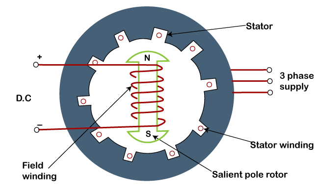
Stator: Similar to the stator of a single-phase induction motor. Contains main winding and auxiliary winding, which are connected to a single-phase AC supply. These windings create a rotating magnetic field.
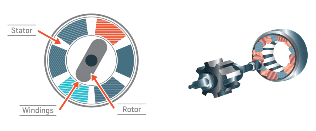
Rotor: A squirrel cage rotor modified by removing some teeth to create salient poles. The salient poles are essential for generating reluctance torque and achieving synchronous operation.
When the single-phase AC supply is applied, the main and auxiliary windings generate a rotating magnetic field. The rotor starts like a squirrel cage induction motor, with the rotating magnetic field inducing currents in the rotor bars. As the rotor accelerates, it tries to align itself with the stator’s magnetic field to minimise magnetic reluctance. However, due to inertia, the rotor overshoots and continuously tries to realign with the rotating field in subsequent cycles. When the rotor speed reaches approximately 75% of the synchronous speed, the auxiliary winding is typically disconnected. At synchronous speed, reluctance torque becomes strong enough to pull the rotor into synchronism with the stator’s rotating magnetic field. The motor then operates as a synchronous motor, and the rotor locks into synchronism with the stator field. The motor runs at synchronous speed due to the synchronous reluctance torque. Unlike an induction motor, there is no slip once the motor reaches synchronous speed.
Advantages: Simple Construction as no windings or permanent magnets on the rotor. Self-Starting so no need for external starting mechanisms. Low Maintenance due to a robust design with minimal wear and tear. Operates at synchronous speed once synchronised.
Disadvantages: Lower Power Factor since they operate with a lagging power factor. Not as efficient as other synchronous motors. Relatively lower and less smooth torque compared to other motor types. Suitable only for specific low-power applications.
Applications: Reluctance motors are commonly used in applications where constant speed is critical and load torque is moderate: Electric Clocks. Recording Instruments. Fans and Blowers. Optical Equipment. Textile Machinery.
Hysteresis motors.
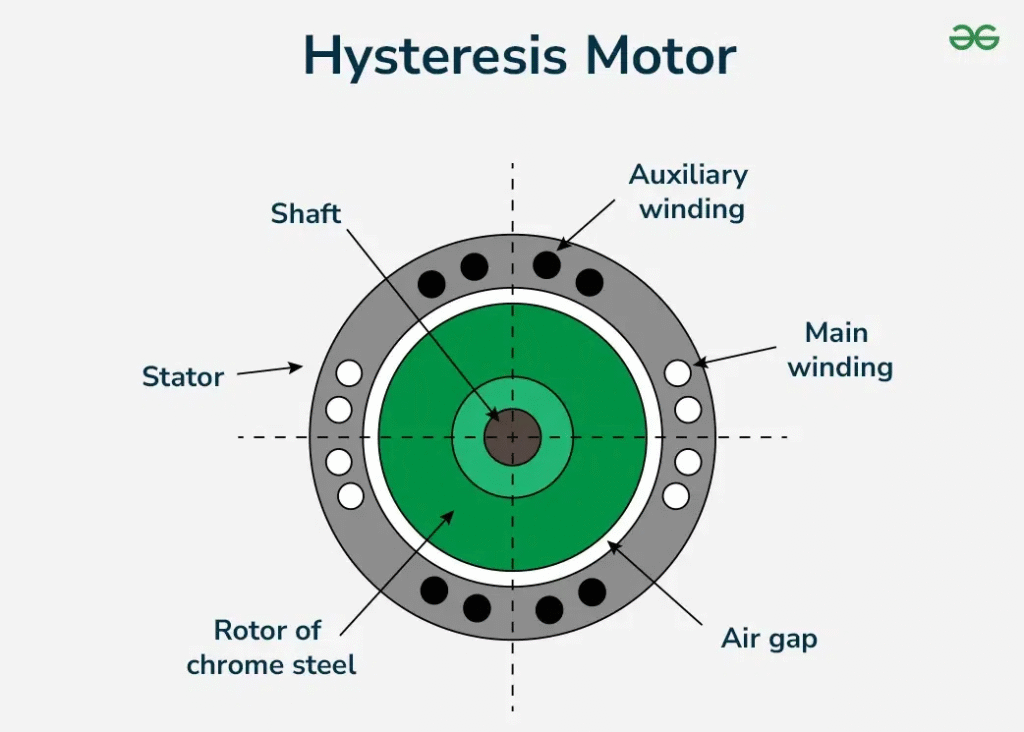
Rotor: Made of ferromagnetic material such as chrome-cobalt steel or alnico. Has high hysteresis loss properties, which are crucial for its operation. Cylindrical in shape with no windings or slots, contributing to quiet operation.
Stator: Powered by a single-phase AC supply.Contains two windings, The Main Winding creates the primary magnetic field and the Auxiliary Winding: Provides the necessary phase shift to produce a rotating magnetic field (similar to a split-phase motor).
When the stator is energised with a single-phase AC supply, the combination of the main and auxiliary windings creates a rotating magnetic field. This rotating magnetic field induces eddy currents in the rotor, causing it to start rotating with a certain slip. The ferromagnetic rotor lags behind the rotating magnetic field due to its hysteresis loss properties. The magnetic polarity of the rotor aligns with the rotating field as it is magnetised and demagnetized repeatedly. As the rotor accelerates, the slip reduces. When the rotor speed matches the synchronous speed of the stator’s magnetic field, the stator “locks” the rotor into synchronism. At this point, the motor runs as a synchronous motor.
Features of Hysteresis Motor:
Self-Starting: Does not require additional starting mechanisms or windings.
Quiet Operation: Due to its smooth construction and lack of slots or brushes.
Constant Speed: Operates at synchronous speed regardless of load.
High Starting Torque: Resulting from the hysteresis and eddy current effects.
Advantages: No mechanical or electrical starting aids are needed. Quiet and vibration-free operation. Constant speed under varying load conditions. High durability due to its robust construction.
Disadvantages: Lower efficiency compared to other synchronous motors. Limited to low power applications. High rotor material cost due to the use of specialised materials like chrome-cobalt or alnico.
Applications: Hysteresis motors are typically used in applications requiring quiet, reliable, and precise operation, such as: Clocks, Record players and turntables, Electric timers, Tape recorders, Optical and medical instruments.
Current-Excited Synchronous Motors
These motors rely on an external DC power source to magnetise the rotor. The rotor contains windings that are connected to a DC power source through slip rings or other means. The DC current produces a constant magnetic field in the rotor. The rotor aligns itself with the stator’s rotating magnetic field, achieving synchronism. They have precise control over the magnetic field, enabling better performance. Can operate at leading, lagging, or unity power factors, depending on the excitation level. Suitable for medium to high-power applications in industrial processes.
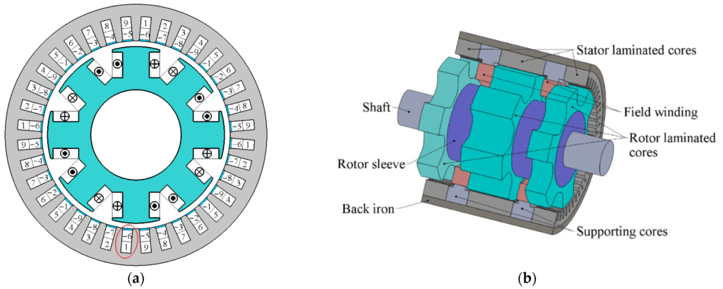
Examples: Large synchronous motors used in power plants and industrial drives.
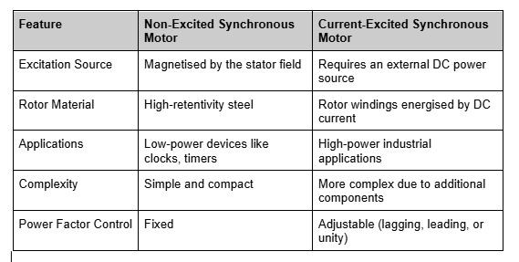
Comparison: Non-Excited vs. Current-Excited Motors
Interested in our Electrical Engineering Courses?
At iLearn Engineering®, we offer a diverse range of online accredited electrical engineering courses and qualifications to cater to different academic and career goals. Our courses are available in varying credit values and levels, ranging from 40 credit Engineering Diplomas to a 360 credit International Graduate Diploma.
Short Courses (40 Credits)
A selection of our more popular 40 credit electrical diplomas…
Diploma in Electrical and Electronic Engineering
Diploma in Electrical Technology
Diploma in Renewable Energy (Electrical)
First Year of Undergraduate (Level 4 – 120 Credits)
Higher International Certificate in Electrical and Electronic Engineering
First Two Years of Undergraduate (Level 5 – 240 Credits)
Higher International Diploma in Electrical and Electronic Engineering.
Degree equivalent Graduate Diploma (Level 6 – 360 Credits)
International Graduate Diploma in Electrical and Electronic Engineering
All Electrical and Electronic Courses
You can read more about our selection of accredited online Electrical and Electronic Engineering courses here.
Complete Engineering Course Catalogue (all courses)
Alternatively, you can view all our online engineering courses here.
Recent Posts
Understanding Key Performance Indicators in Manufacturing
Understanding Key Performance Indicators in Manufacturing Introduction Key Performance Indicators (KPIs), or sometimes written as Key Performance Measures, are some of the key ‘metrics’ that are used to measure the performance of an industrial system. A good KPI for a manufacturing system should be SMART, that is: Specific – It should measure a specific output […]
How Aircraft Structures Evolved: From Fragile Flyers to Engineering Masterpieces
How Aircraft Structures Evolved: From Fragile Flyers to Engineering Masterpieces Introduction As with all other aspects involved with an aircraft, the structural design and layout has changed markedly over the history of flight, in line with technological advances and new discoveries. This section will highlight some of the more substantial developments made during the history […]
Why Lean Manufacturing Matters: Principles of waste
Why Lean Manufacturing Matters: Principles of waste Introduction Lean manufacturing isn’t just a toolkit for improving efficiency, it’s a mindset that reshapes how organisations think about value. At its core, lean focuses on delivering exactly what the customer needs, when they need it, with as little waste as possible. In an increasingly competitive and resource-conscious […]