Mastering the Glide: How Aircraft Fly Without Thrust
Introduction
Gliding flight demonstrates how an aircraft can remain airborne without engine thrust by efficiently balancing lift, drag, and weight. Whether in engine-out scenarios or in glider operations, understanding the principles of glide performance is essential for pilots and engineers alike. Factors such as glide ratio, angle of attack, airspeed, and aircraft configuration play a crucial role in determining how far and how efficiently an aircraft can travel without power. This article explores the aerodynamic principles behind gliding flight and explains how aircraft are able to sustain controlled, stable flight without thrust
Gliding is a term applied to the flight of an aircraft where there is no power, or thrust, delivered from the engines. If we consider the forces acting upon the aircraft below, we can neglect the thrust.
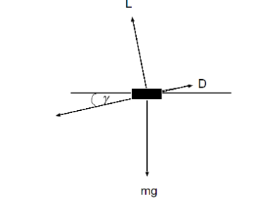
Generating expressions for lift and drag, by balancing the forces above, gives:
D = W sin γ
L = W cos γ
Where γ is the glide angle.
Dividing these 2 expressions gives us a very useful parameter D/L.
D/L = W sin γ / W cos γ = tan γ
tan γ = D/L = CD / CL
Example 1: Calculating Glide Angle from Aerodynamic Coefficients
Given: Lift coefficient, CL= 0.6, Drag coefficient, CD= 0.03
Calculation:
Tan γ = CD/ CL = 0.03 / 0.6 = 0.05
γ = tan−1(0.05) ≈ 2.86º
The glide angle γ is approximately 2.86°.
Example 2: Finding Drag-to-Lift Ratio and Glide Angle
Given: Lift L = 20 000 N, Drag D = 1 000 N
Calculation:
D/L = 1 000 / 20 000 = 0.05
tan γ = 0.05 ⇒ γ =tan−1(0.05) ≈ 2.86º
The aircraft descends at a glide angle of 2.86°.
Example 3: Calculating Lift Coefficient for a Given Glide Angle
Given: Drag coefficient CD = 0.04, Glide angle γ = 4º
Calculation:
tan4º ≈ 0.0699
CL = CD / tan γ = 0.04 / 0.0699 ≈ 0.57
Required lift coefficient is CL ≈ 0.57
This is a useful equation which tells us that as drag increases and lift decreases the ratio D/L gets bigger – this also corresponds to an increase in the glide angle. Another way of looking at it is, as the lift increases and drag decreases for an aircraft, the Lift to drag ratio L/D increases and the glide angle minimises.
Minimising the glide angle is important for an aircraft as it determines how far the aircraft will glide with the absence of engine power. It can also be thought of as the efficiency of the aircraft, where in this sense the efficiency is maximising the lift produced compared to the drag produced.
It will be noticed that this is the same criterion as for maximum range, so that an aeroplane that has a flat gliding angle should also be efficient at flying for range, neglecting the influence of the propulsion efficiency.
If an aeroplane is to glide as far as possible, the angle of attack during the glide must be such that the lift/drag is a maximum. If the pilot attempts to glide at an angle of attack either greater or less than that which gives the best L/D, then in each case the path of descent will be steeper.
To summarise:
- We want to know how far the aircraft can travel in gliding flight.
- For maximum distance the glide angle is minimised.
- Aircraft must fly at velocity and angle of attack to minimise glide angle and hence minimum CD / CL
We can also find the glide range of an aircraft by considering the diagram below.
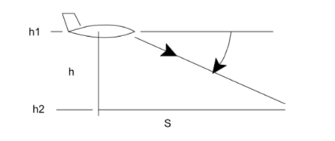
The glide range can be calculated as follows:
tan γ = h / S
S = (h1-h2) / tan γ
Subbing in for L/D:
S = L/D ( h1-h2)
Example: Find the glide range for an aircraft that has an altitude of 2.5km. The aircraft has a lift to drag ratio L/D of 15.
Solution:
S = L/D ( h1-h2)
S = 15 ( 2500 – 0)
S = 37500m
We can see here from this answer that for every 1000m the aircraft descends it is covering 15000m horizontally or 15 times as much.
Minimum Glide Angle
Since the mathematical relationship between glide angle and lift and drag coefficients is:
tan γ = CD / CL
If we express CD / CL = (CDO + kCL2 ) / CL
We can differentiate CD/CL and make this equal to zero, giving the minimum value of this function. After some algebraic manipulation the minimum value of CD/CL
is given by 2 √kCDO Hence the minimum glide angle is given by:
γ min = tan -1 ( 2 √kCDO )
Where;
K = 1 / πARe (1 over the effective aspect ratio)
CDO is the drag coefficient at zero lift
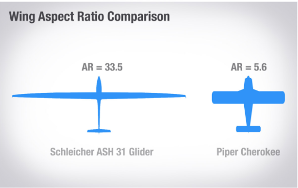
It can then be seen to minimise the glide angle one must increase the effective aspect ratio (as this will reduce the value of k)
The diagram below shows how aspect ratio changes for various wing designs. It can be seen that the longer wings have a much higher aspect ratio and hence a smaller minimum glide angle.
The zero-lift drag coefficient is reflective of parasitic drag which makes it very useful in understanding how “clean” or streamlined an aircraft’s aerodynamics are. The zero-lift drag coefficient can be minimised by streamlining the design of an aircraft. The removal or redesign of drag-inducing structures such as landing gear, engines and radiators, struts and wires, open cockpits, and armament could greatly increase the performance of both civilian and military aircraft.
Example: A sailplane with a mass of 500kg has a drag polar equation CD = CDO + kCL2 where the value of CDO is 0.01 , the value of k is 0.022 and the lift coefficient is 0.75. Find the lift to drag ratio and the minimum glide angle.
Solution:
CD = 0.01 + 0.022 x 0.752
CD = 0.0233
The lift to drag ratio is therefore:
L/D = CL/DC = 0.75 / 0.0233 = 33.6
We can also find the minimum glide angle with:
γ min = tan -1 ( 2 √kCDO )
γ min = tan -1 ( 2 √0.022 x 0.01 )
γ min = 1.7º
Speed for Minimum Rate of Descent
With some consideration to the forces applied on an aircraft in glide and algebraic manipulation we can determine the velocity required for the minimum rate of descent, vmin
Vmin = 4(2w/ρ)½ ( k3CDO / 27 ) 1/4
In this equation one must consider: ρ,the air density. wing loading, w. the constant k and the drag at zero lift CDO
wing loading is the total mass of an aircraft divided by the area of its wing.
Example: Worked example (sea level)
Given: Weight: W = 150,000 N, Air density: ρ = 1.225 kg m−3, Induced-drag factor: k = 0.05, Zero-lift drag coefficient: CD0 = 0.025
Calculating the first bracket
(2w/ρ)½ = ( 2×150000 / 1.225) 1/2
(2w/ρ)½ = (300000/1.225) ½
(2w/ρ)½ = ( 244897.96)½ = 494.87
Calculating the second bracket
( k3CDO / 27 ) ¼ =( (0.05)3 ( 0.025) / 27 )¼
( k3CDO / 27 ) ¼= ( 3.125 x 10⁻⁶ / 27 ) ¼
( k3CDO / 27 ) ¼ = 0.01844
So the final calculation
V min = 4 x 494.87 x 001844
V min = 36.51ms-1
Converting to Knots
36.51 x 1.94 = 79.97knots
Interested in our Aerospace Engineering Courses?
At iLearn Engineering®, we offer a diverse range of online accredited aerospace engineering courses and qualifications to cater to different academic and career goals. Our aerospace courses are available in varying credit values and levels, ranging from 40 credit Engineering Diplomas to a Bachelor’s equivalent 360 credit International Graduate Diploma.
All Aerospace Engineering Courses
All Aerospace Engineering Diploma Courses can be seen here.
Short Aerospace Courses (40 Credits)
- Diploma in Aerospace Engineering
- Diploma in Aircraft Design
- Diploma in Principles of Flight
- Diploma in Aerospace Structures
- Diploma in Aerodynamics
- Diploma in Aerodynamics, Propulsion and Space
First Year of Undergraduate (Level 4 – 120 Credits)
Higher International Certificate in Aerospace Engineering
Years One and Two of Undergraduate (Level 5 – 240 Credits)
Higher International Diploma in Aerospace Engineering
Degree Equivalent International Graduate Diploma (Level 6 – 360 Credits)
International Graduate Diploma in Aerospace Engineering
Complete Engineering Course Catalogue (all courses)
Alternatively, you can view all our online engineering courses here.
Recent Posts
Civil Engineering Courses and Diplomas: Topics, Skills and Career Routes
Civil Engineering Courses and Diplomas: Topics, Skills and Career Routes Introduction Civil engineering is the backbone of modern society. From roads and bridges to skyscrapers and water systems, civil engineers design, build, and maintain the infrastructure that keeps the world running. If you’re considering a civil engineering course or diploma, understanding what it covers is […]
What Is a Diploma in Engineering? Courses, Levels and Career Routes Explained
What Is a Diploma in Engineering? Courses, Levels and Career Routes Explained Introduction Engineering shapes the world around us, from the buildings we live in to the technology we use every day. But for many aspiring engineers, the biggest question is not whether to pursue engineering, but how to start. Traditional university degrees are not […]
Engineering Courses: How to Choose the Right Route for Your Career
Engineering Courses: How to Choose the Right Route for Your Career Introduction Choosing an engineering course can feel like standing at the beginning of several different roads, each leading towards a different kind of future. One route may lead into mechanical systems and manufacturing. Another may lead towards aircraft, infrastructure, electronics, computing, renewable energy or […]