

How Wind Tunnels Use Pressure Measurements to Test Aircraft Aerodynamics
Before an aircraft, wing or engine intake is built at full scale, engineers need evidence of how air will move around it. A wind tunnel provides that evidence by moving controlled airflow past a model and measuring the pressure, forces and flow behaviour that result.
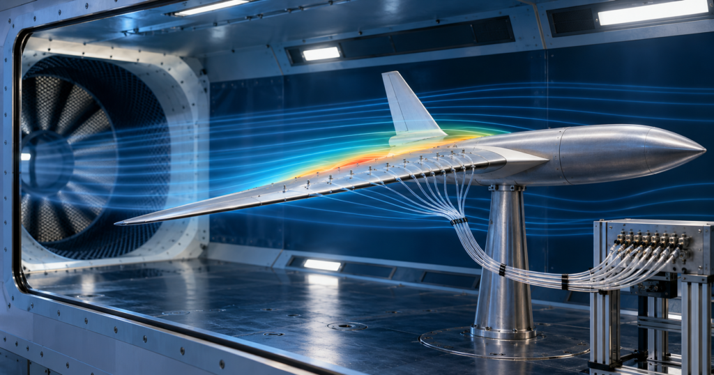
Pressure measurements are particularly valuable because they reveal far more than airspeed alone. They show where airflow accelerates, where pressure recovers, how strongly an aerofoil is loaded, and whether an intake, fairing or control surface is producing an unwanted loss.
What happens inside a wind tunnel?
A conventional wind tunnel guides air through several sections before it reaches the test model. The arrangement varies by facility, but the airflow commonly passes through a settling chamber, screens or honeycombs, a contraction, the test section and then a diffuser.
The aim is to produce airflow in the test section that is as uniform and controlled as possible. The model is mounted in this section, where instruments record the aerodynamic response.
Insert image: wind-tunnel-pressure-measurements-test-section.png here
The basic relationship between airflow area and velocity is the continuity equation:
Q = A × V
Where:
- Q is volume flow rate in m³/s
- A is cross-sectional area in m²
- V is average airflow velocity in m/s
For steady incompressible flow, the same volume of air must pass through each section of the tunnel every second. If the area reduces in the contraction, the velocity must increase.
This is why a wind tunnel can use a large, slow-moving settling region before a narrower, faster test section. The contraction does not create mass flow; it changes the velocity required for the existing flow rate to pass through a smaller area.
Why pressure changes as the air accelerates
For low-speed airflow, where density changes are small, Bernoulli’s equation relates velocity and pressure:
P + ½ρV² + ρgz = constant
Where:
- P is static pressure
- ρ is air density
- V is airflow velocity
- g is gravitational acceleration
- z is height
Within a horizontal section of a low-speed wind tunnel, the height term is often negligible. If the airflow accelerates through a contraction, its dynamic-pressure term rises. In an ideal flow, this corresponds to a reduction in static pressure.
This relationship is useful, but it should not be treated as a complete description of a real tunnel. Viscosity, wall friction, turbulence, flow separation and losses through screens or bends all affect the pressure available at the test section.
The pressure measurements engineers use
Static pressure
Static pressure is the pressure that would be measured when the sensing hole is not facing directly into the flow. On a wind-tunnel model, small pressure taps can be placed across the surface of an aerofoil, intake or fuselage section.
A set of pressure taps makes it possible to plot how pressure changes from the leading edge to the trailing edge. That pressure distribution helps engineers understand the aerodynamic loading on the component.
Total pressure
Total pressure, sometimes called stagnation pressure, is measured where moving air is brought to rest without a major loss of energy. A probe facing directly into the flow can provide this measurement.
The difference between total pressure and static pressure is linked to dynamic pressure:
q = P₀ − P = ½ρV²
Where:
- q is dynamic pressure
- P₀ is total pressure
- P is static pressure
For incompressible low-speed flow, this relationship can be rearranged to estimate velocity:
V = √(2q / ρ)
Pressure rakes and pitot-static probes
A pitot-static probe combines a forward-facing total-pressure opening with static-pressure ports. In a wind tunnel, the probe can be placed in the freestream to check the test-section velocity.
A pressure rake contains several sensing points. It can measure how total or static pressure varies across a region, such as the wake behind a wing or the flow entering an engine intake.
For a wider introduction to the same measurement principle on an aircraft, see how aircraft airspeed and altitude are measured.
A simple test-section airspeed calculation
Consider an illustrative low-speed wind-tunnel test. A pitot-static probe records a total-to-static pressure difference of 500 Pa. The test-section air density is 1.20 kg/m³.
V = √(2 × 500 / 1.20)
V = 28.9 m/s
The calculated test-section velocity is therefore approximately 29 m/s.
This calculation is suitable as a first estimate when the flow can reasonably be treated as incompressible. At higher Mach numbers, density changes become increasingly important and compressible-flow methods are required.
How pressure data reveals aerodynamic performance
Pressure data is most useful when it is interpreted as a pattern rather than as a single reading.
On an aerofoil, low pressure over the upper surface and comparatively higher pressure beneath it contribute to the net aerodynamic force. Measuring the pressure at many points helps engineers identify:
- the leading-edge suction peak;
- pressure recovery along the upper surface;
- regions where an adverse pressure gradient may encourage separation;
- changes caused by flap deflection, angle of attack or surface modifications; and
- the difference between alternative aerofoil profiles.
NASA notes that wind-tunnel models may be fitted with pressure taps to calculate component performance, while static-pressure taps and total-pressure rakes can also be used to diagnose the flow around and through a model. [1]
Insert image: wind-tunnel-pressure-taps-aerofoil.png here
Why the wake matters
The airflow behind a model can reveal losses that are not immediately obvious from the flow approaching it. As a wing produces lift and drag, it leaves a wake with altered velocity and total pressure.
A total-pressure rake positioned downstream of an aerofoil can measure the pressure deficit across that wake. This data can be used to investigate profile drag and compare changes in geometry, surface condition or angle of attack.
The test therefore becomes more than a simple question of “How much lift did the wing generate?” It can help answer “Where is the loss occurring, and what feature of the flow is causing it?”
That distinction is important in aircraft design, where a small local pressure loss can affect an intake, cooling system, control surface or overall aerodynamic efficiency.
Limits of pressure-based wind-tunnel measurements
Pressure measurements are powerful, but they must be planned carefully. Engineers need to consider several limitations.
First, the presence of the model itself changes the flow within the test section. If the model occupies too much of the available area, blockage effects can distort the result.
Second, a probe or pressure tap measures conditions only where it is located. A small number of readings can miss a strong gradient, separation region or wake feature.
Third, similarity matters. The tunnel test should represent relevant values of Mach number, Reynolds number, angle of attack and surface condition as closely as possible. A model at the correct speed but the wrong Reynolds number may not reproduce the same boundary-layer behaviour as the full-scale aircraft.
Finally, low-speed equations should not be extended carelessly into transonic or supersonic conditions. Once compressibility, shock waves or large temperature changes become important, the analysis must change with them.
From pressure readings to design decisions
Wind tunnels allow aerospace engineers to turn invisible airflow into measurable evidence. Continuity explains how tunnel geometry changes velocity; Bernoulli’s principle links velocity and pressure in appropriate low-speed conditions; and pressure instrumentation shows what the flow is actually doing around the model.
The result is a disciplined route from measurement to design decision: identify a pressure pattern, understand the flow mechanism behind it, modify the geometry, then test again.
Learners who want to explore aerofoils, aircraft flow, drag, propulsion and high-speed flight in more depth can study the 40-credit Diploma in Aerodynamics, Propulsion and Space. For a broader aerospace route, iLearn Engineering® also offers the Higher International Diploma in Aerospace Engineering and the International Graduate Diploma in Aerospace Engineering.
Frequently asked questions
Do wind tunnels measure lift and drag directly?
They can. A model may be mounted on a calibrated force balance that measures forces and moments directly. Pressure measurements can then add detail about why those forces occur and where flow losses develop. [1]
Does a wind tunnel always use a pitot tube?
No. Pitot-static probes are common for measuring freestream conditions, but wind tunnels can also use pressure taps, pressure rakes, force balances, laser-based measurement systems and flow-visualisation methods.
Can Bernoulli’s equation be used for every wind-tunnel test?
No. It is most useful as a low-speed, incompressible-flow approximation. Tests involving significant compressibility, shock waves or high temperature require more advanced aerodynamic analysis.
References
[1] NASA Glenn Research Center, “Wind Tunnel Testing”
Interested in our Aerospace Engineering Courses?
At iLearn Engineering®, we offer a diverse range of online accredited aerospace engineering courses and qualifications to cater to different academic and career goals. Our aerospace courses are available in varying credit values and levels, ranging from 40 credit Engineering Diplomas to a Bachelor’s equivalent 360 credit International Graduate Diploma.
All Aerospace Engineering Courses
All Aerospace Engineering Diploma Courses can be seen here.
Short Aerospace Courses (40 Credits)
- Diploma in Aerospace Engineering
- Diploma in Aircraft Design
- Diploma in Principles of Flight
- Diploma in Aerospace Structures
- Diploma in Aerodynamics
- Diploma in Aerodynamics, Propulsion and Space
First Year of Undergraduate (Level 4 – 120 Credits)
Higher International Certificate in Aerospace Engineering
Years One and Two of Undergraduate (Level 5 – 240 Credits)
Higher International Diploma in Aerospace Engineering
Degree Equivalent International Graduate Diploma (Level 6 – 360 Credits)
International Graduate Diploma in Aerospace Engineering
Complete Engineering Course Catalogue (all courses)
Alternatively, you can view all our online engineering courses here.
Recent Posts
Electrical and Electronic Engineering Courses and Diplomas: A Complete Guide
Electrical and Electronic Engineering Courses and Diplomas: A Complete Guide Introduction: Electrical and electronic engineering courses teach learners how electrical power, circuits, machines, electronic devices and control systems operate. The right course depends on whether the learner wants to study a focused subject, establish a broad foundation at Level 4, progress to Level 5 or […]
What Are Complex Numbers and Why Do Engineers Use Them?
What Are Complex Numbers and Why Do Engineers Use Them? Complex numbers can appear abstract when they are first encountered. After all, how can the square root of a negative number represent anything useful in the real world? For engineers, complex numbers are not merely a mathematical curiosity. They provide an efficient way to represent […]
Pascal’s Law Explained: How Hydraulic Systems Multiply Force
Pascal’s Law Explained: How Hydraulic Systems Multiply Force How can a relatively small force applied to a brake pedal, jack handle or hydraulic control move a much heavier load? The answer is Pascal’s law. When pressure is applied to a confined fluid, the resulting pressure change is transmitted throughout the fluid. If that pressure acts […]