

Induced Drag Explained: Why Flying Slower Can Increase Drag
Why can an aircraft experience more drag when it flies more slowly? We usually associate greater speed with greater air resistance, but a wing must also generate enough lift to support the aircraft.
Induced drag is the drag associated with producing lift on a finite-span wing. When an aircraft slows down while maintaining the same lift, its induced drag increases, provided air density and wing characteristics remain unchanged.

This relationship helps explain why aircraft designers pay so much attention to wingspan, why gliders have long wings, and why reducing airspeed does not always reduce total drag.
What causes induced drag?
A lifting wing creates a pressure difference between its upper and lower surfaces. Near the wing tips, air moves around the tips from the higher-pressure region beneath the wing towards the lower-pressure region above it.
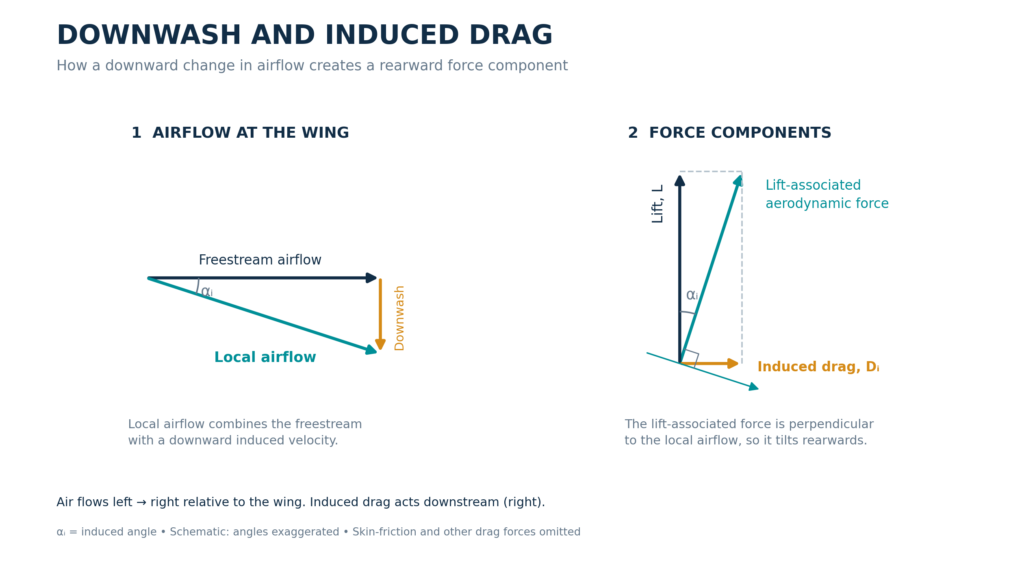
The resulting flow forms a trailing vortex system, including the familiar pair of counter-rotating wingtip vortices. This system produces downward airflow, called downwash, which changes the local airflow direction experienced by the wing.
The aerodynamic force associated with lift is inclined backwards relative to the undisturbed airflow. Its rearward component is induced drag. NASA describes this as an additional drag component associated with a finite, lifting wing. 1
Wingtip vortices are therefore part of a wider three-dimensional flow pattern. Understanding induced drag requires considering how lift is distributed across the whole wingspan.
For an introduction to the complete aircraft force balance, read The Four Fundamental Forces that Enable Aircraft to Fly.
Why does induced drag increase at lower airspeed?
Consider an aircraft maintaining steady, straight and level flight. In a simplified force balance, lift equals weight.
Lift can be calculated using:
L = ½ × ρ × V² × S × Cₗ
Where:
- L = lift, in newtons.
- ρ = air density, in kg/m³.
- V = true airspeed, in m/s.
- S = wing reference area, in m².
- Cₗ = lift coefficient, which is dimensionless.
The equation shows that lift depends on airspeed squared. If the aircraft slows down while air density and wing area remain unchanged, its lift coefficient must increase to maintain the same lift.
For an unchanged wing configuration, this normally means increasing the angle of attack within the unstalled operating range. The lift coefficient represents how effectively the wing generates lift at its particular operating condition. 2
Increasing lift coefficient also increases the induced drag coefficient. The relationship is:
Cdi = Cₗ² / (π × AR × e)
Where:
- Cdi = induced drag coefficient.
- Cₗ = lift coefficient.
- AR = wing aspect ratio.
- e = span-efficiency factor.
- π ≈ 3.1416.
The span-efficiency factor accounts for the effect of the lift distribution across the span. In the classical planar-wing model, an elliptical lift distribution gives e = 1. 1
However, drag coefficient and drag force are different quantities. To determine the actual force, the coefficient must be combined with dynamic pressure and reference area.
The induced drag equation
Combining the lift and drag relationships with the definition of aspect ratio gives:
Dᵢ = 2 × L² / (ρ × V² × π × e × b²)
Where:
- Dᵢ = induced drag force, in newtons.
- L = lift, in newtons.
- ρ = air density, in kg/m³.
- V = true airspeed, in m/s.
- e = span-efficiency factor.
- b = wingspan, in metres.
This expression follows from the standard coefficient relationship and the aerodynamic force equations. 1 3
The equation reveals three useful relationships:
| Change | Effect on induced drag | Other quantities held constant |
|---|---|---|
| Increase lift | Induced drag increases with lift squared | Density, airspeed, wingspan and span efficiency |
| Increase airspeed | Induced drag decreases with airspeed squared | Lift, density, wingspan and span efficiency |
| Increase wingspan | Induced drag decreases with wingspan squared | Lift, density, airspeed and span efficiency |
These conditions matter. The statement “induced drag decreases as speed increases” assumes that the required lift remains constant.
Worked example: calculating induced drag
Consider an illustrative aircraft in steady, straight and level flight.
| Quantity | Value |
|---|---|
| Aircraft mass | 75,000 kg |
| Wingspan | 36 m |
| Air density | 0.70 kg/m³ |
| True airspeed | 230 m/s |
| Assumed span-efficiency factor | 0.80 |
These are teaching values rather than verified performance data for a particular aircraft. Assume the wing provides lift equal to the aircraft’s weight.
Step 1: Calculate the lift required
L = mass × gravitational acceleration
L = 75,000 × 9.81
L = 735,750 N
Step 2: Calculate induced drag
Dᵢ = 2 × 735,750² / (0.70 × 230² × π × 0.80 × 36²)
Dᵢ ≈ 8,976 N
The estimated induced drag is therefore 8.98 kN.
Step 3: Reduce the airspeed
Now reduce true airspeed to 200 m/s, keeping the aircraft’s required lift, air density, wingspan and span-efficiency factor unchanged.
Dᵢ = 2 × 735,750² / (0.70 × 200² × π × 0.80 × 36²)
Dᵢ ≈ 11,871 N
| True airspeed | Estimated induced drag |
|---|---|
| 230 m/s | 8.98 kN |
| 200 m/s | 11.87 kN |
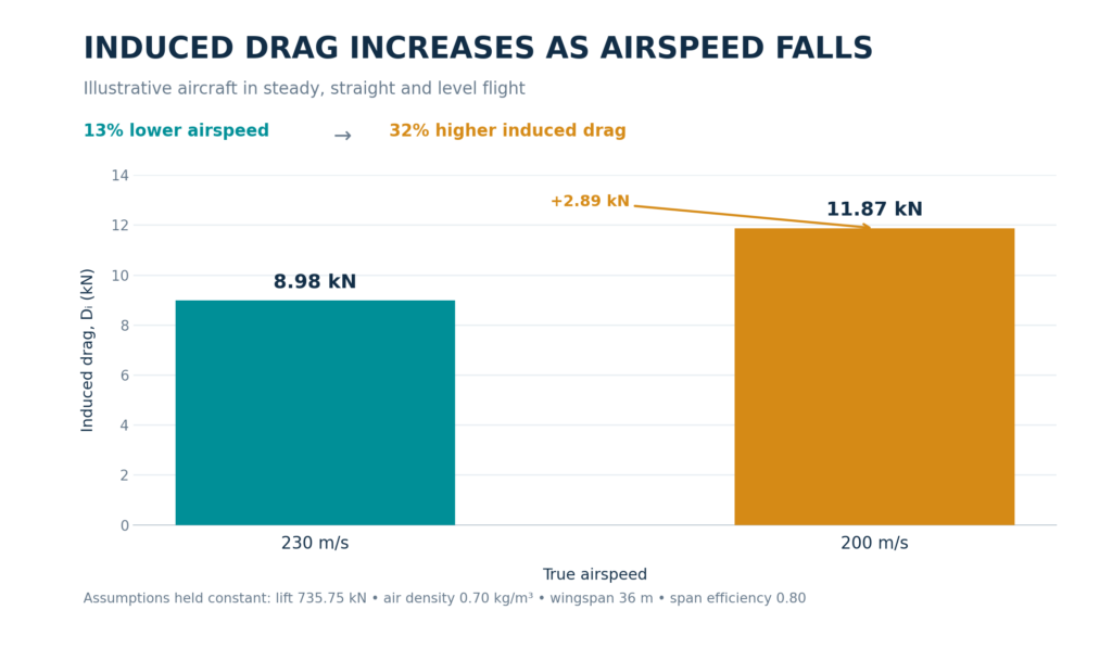
A reduction in airspeed of approximately 13% has increased induced drag by approximately 32%.
The aircraft still needs the same lift, but it must generate that lift at a lower speed. This changes the aerodynamic operating condition and increases the induced-drag component.
The calculation estimates induced drag only. It does not predict total aircraft drag or account for changes in span efficiency, compressibility effects or aircraft configuration.
Induced drag versus parasite drag
Parasite drag includes skin-friction drag, form drag and interference drag. These arise from the aircraft’s surfaces, shape and interactions between the airflow around its components.
Induced drag is specifically associated with generating lift on a finite wing.
For a fixed configuration, the two components behave differently as airspeed changes:
| Feature | Induced drag | Parasite drag |
|---|---|---|
| Main association | Producing lift on a finite wing | Surface friction, body shape and component interactions |
| Simplified speed relationship | Decreases as speed increases at constant lift | Increases as speed increases at constant drag coefficient |
| Important influences | Required lift, wingspan and lift distribution | Surface condition, geometry and flow conditions |
| Typical design approaches | Adjust span, lift distribution or wingtip design | Improve streamlining, surface finish or component junctions |
The familiar square-of-speed increase in parasite drag follows from the drag equation when density, reference area and drag coefficient remain constant. In practice, drag coefficients can change with operating conditions. 3
This explains why flying faster does not keep reducing total drag indefinitely. The reduction in induced drag must be considered alongside the increase in other drag components.
For more detail on surface friction and flow separation, see Laminar vs Turbulent Boundary Layers: Why Airflow Separates from Aircraft Wings.
How do longer wings and winglets help?
Wing aspect ratio is calculated as:
AR = b² / S
Here, b is wingspan and S is wing area.
Increasing span while maintaining the same wing area produces a higher aspect ratio. Long, slender wings can reduce induced drag, helping explain their use on gliders and other aircraft designed for efficient flight. Winglets provide another approach by modifying the flow near the wing tips. 4
Neither approach should be considered in isolation. Longer wings affect structural loads and practical dimensions. Winglets add surface area and must be integrated with the wing; an unsuitable design can increase overall drag. 4
These compromises are explored in Why There Is No Perfect Aerofoil: The Design Trade-Offs Behind Every Aircraft Wing.
Develop your knowledge of aerodynamics
Understanding induced drag helps you connect airflow theory with aircraft performance and wing design.
The Diploma in Aerodynamics from iLearn Engineering® is a 40-credit Level 6 course covering aerodynamic forces, aerofoils and wings, boundary-layer behaviour and high-speed aerodynamics.
For a Level 5 option that also includes propulsion and spaceflight, the Diploma in Aerodynamics, Propulsion and Space covers airflow around aircraft, drag and its minimisation, gas turbine propulsion and high-speed flow.
Broader aerospace study is available through the Higher International Certificate, Higher International Diploma and International Graduate Diploma in Aerospace Engineering.
Explore the Diploma in Aerodynamics to view the course content and study options.
Frequently asked questions
Does induced drag disappear at high speed?
No. A finite wing producing lift still generates induced drag. Under constant-lift conditions, increasing airspeed reduces its magnitude, but does not eliminate it.
Does a heavier aircraft produce more induced drag?
In steady, level flight, greater weight requires greater lift. With airspeed, density and wing characteristics unchanged, induced drag increases with lift squared. In the simplified model, a 10% increase in required lift produces a 21% increase in induced drag.
Is induced drag directly proportional to angle of attack?
Not generally. The standard relationship makes induced drag coefficient proportional to lift coefficient squared. Angle of attack influences lift coefficient, but describing induced drag as simply proportional to angle of attack is inaccurate.
Do winglets eliminate induced drag?
No. Winglets can reduce induced drag by changing the wingtip flow, but their effectiveness depends on the complete wing design. They do not eliminate the aerodynamic cost of producing lift. 4
References
- NASA Glenn Research Center — Induced Drag Coefficient
- NASA Glenn Research Center — Lift Equation
- NASA Glenn Research Center — Drag Equation
- NASA Glenn Research Center — Winglets
Interested in our Aerospace Engineering Courses?
At iLearn Engineering®, we offer a diverse range of online accredited aerospace engineering courses and qualifications to cater to different academic and career goals. Our aerospace courses are available in varying credit values and levels, ranging from 40 credit Engineering Diplomas to a Bachelor’s equivalent 360 credit International Graduate Diploma.
All Aerospace Engineering Courses
All Aerospace Engineering Diploma Courses can be seen here.
Short Aerospace Courses (40 Credits)
- Diploma in Aerospace Engineering
- Diploma in Aircraft Design
- Diploma in Principles of Flight
- Diploma in Aerospace Structures
- Diploma in Aerodynamics
- Diploma in Aerodynamics, Propulsion and Space
First Year of Undergraduate (Level 4 – 120 Credits)
Higher International Certificate in Aerospace Engineering
Years One and Two of Undergraduate (Level 5 – 240 Credits)
Higher International Diploma in Aerospace Engineering
International Graduate Diploma (Level 6 – 360 Credits)
International Graduate Diploma in Aerospace Engineering
Complete Engineering Course Catalogue (all courses)
Alternatively, you can view all our online engineering courses here.
Recent Posts
Laminar vs Turbulent Boundary Layers: Why Airflow Separates from Aircraft Wings
Laminar vs Turbulent Boundary Layers: Why Airflow Separates from Aircraft Wings Airflow around an aircraft wing is often shown as smooth streamlines passing neatly over the aerofoil. In reality, the thin layer of air immediately next to the wing surface behaves very differently from the undisturbed airflow further away. This region is called the boundary […]
Why There Is No Perfect Aerofoil: The Design Trade-Offs Behind Every Aircraft Wing
Why There Is No Perfect Aerofoil: The Design Trade-Offs Behind Every Aircraft Wing If a designer could create a perfect aerofoil, it would produce very high lift with almost no drag, remain stable at every angle of attack, fit a lightweight structure inside the wing and work equally well at low and high speed. No […]
How Aerofoils Generate Lift: A Beginner’s Guide to Angle of Attack, Camber and Pressure Distribution
How Aerofoils Generate Lift: A Beginner’s Guide to Angle of Attack, Camber and Pressure Distribution An aerofoil does not create lift simply because its upper surface is curved. Lift is produced because the aerofoil meets the airflow at a suitable angle and shape, causing a pressure distribution that results in an aerodynamic force. For aircraft […]