Aircraft Basics: Main Components and Standard Control Surfaces Explained
Introduction
In this blog we will identify the main components within an aircraft, more from the point of view of large external parts, more specifically, flight control surfaces. Flight control surfaces are simply physical devices that the pilot can control and adjust in order to change the roll, pitch and yaw of an aircraft. Roll, pitch and yaw are terms that relate to movement around the three primary axes that define aircraft movement.
In figure 1 we can see that there are three primary axes which are the longitudinal axis, lateral axis and vertical axis. Sometimes these can be referred to as x, y and z axes.
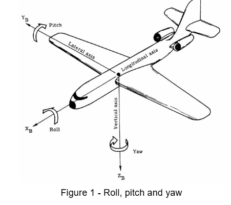
Movement around the longitudinal axis is called roll. A positive roll involves lifting the left wing and lowering the right. When the aircraft rolls in this way it is said to be banking.
Pitch is rotation around the lateral axis and movement that results in an aircraft nose up is positive pitch. An aircraft with positive pitch will be climbing and when nose down with negative pitch it will be descending.
Finally, yaw is rotation around the vertical axis. Positive yaw is when the nose of the aircraft points to the right and the aircraft is said to be turning right. Negative yaw would turn the aircraft left.
Now that we have defined the type of motion for aircraft around the three primary axes we can begin to identify how the pilot creates the motion provided by the control surfaces and identify key sections of the aircraft.
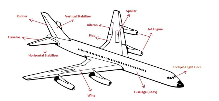
Fuselage, Wings and Tail Section
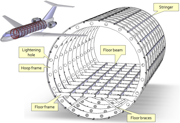
We can begin by discussing the body of the aircraft, which is referred to as the fuselage. Simply speaking the fuselage has the function of transporting cargo and passengers to a destination. It has to accomplish this in often extreme conditions at high altitudes and so must remain pressurised and sufficiently heated.
The fuselage is hollow to reduce weight. As with most other parts of the aeroplane, the shape of the fuselage is normally determined by the mission of the aircraft. A supersonic fighter plane has a very slender, streamlined fuselage to reduce the drag associated with high speed flight. An airliner has a wider fuselage to carry the maximum number of passengers. On an airliner, the pilots sit in a cockpit at the front of the fuselage. Passengers and cargo are carried in the rear of the fuselage.
The wings of an aircraft are responsible for providing the lift force required for flight to take place. This is perhaps their primary function and it is accomplished through specific designs in their shape, or profile.
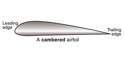
The side on view of a wing is often the most used and in the above image we have a typical aerofoil, or airfoil, section. The trailing edge is that which is more aft than the leading edge, which is in a forward position. We will refer to the front of the aircraft as forward and to the rear as aft. Outboard direction is towards the wing tip and inboard is towards the fuselage.
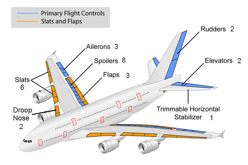
In addition to providing lift, the wings also contain other moving control surfaces such as the spoilers, flaps, slats and ailerons, the function of which are discussed below. In most modern commercial aircraft the engines will also be situated on the underside of the wing. They also perform the important function of storing the fuel of an aircraft and during the course of flight this fuel is often moved around the wings with pumps and directed towards the engines in a way that maintains balance.
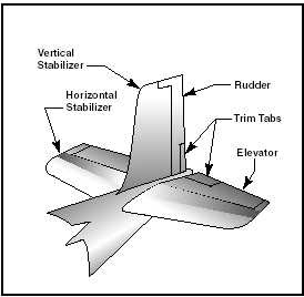
The tail section pictured above refers to the aft portion of the aircraft usually consisting of the horizontal and vertical stabiliser. As the name suggests the function of which is to provide stability in these directions. The rudder is situated on the vertical fin and the elevators on the horizontal. This whole tail assembly is sometimes referred to as the empennage, a derivation of the French word empenner, meaning to feather an arrow.
Flaps and Slats
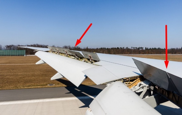
One possible way of increasing the lift generated from a wing section is to increase the wing area and change the profile of the aerofoil section. In order to achieve this aircraft have moving parts at the front and rear of the wing section. Moving parts at the rear are called flaps, they are positioned on the inner wing section, closer to the fuselage on the trailing edge of the wing. Slats on the other hand are positioned on the leading edge of the wing, sometimes positioned along the majority of the leading edge.
Flaps are referred to as high lift devices, when required, they can extend fully to increase the camber and overall wing area. This has the effect of increasing the maximum lift coefficient and hence the lift the aircraft can produce. As the aircraft is producing more lift for a given speed this has the effect of reducing the stall speed, or the speed at which the aircraft can generate sufficient lift for flight. The increase in camber also increases the wing drag, which can be beneficial during approach and landing, because it allows the aircraft to descend at a steeper angle.
There are many different types of flap configurations for aircraft. With each type of design there are associated advantages, mostly to do with increasing the maximum lift and drag at required times.
Ailerons
Whilst flaps and slats are primarily used to increase lift and drag for take off and landing, ailerons are used to orient the aircraft during flight. They are situated in an outboard position on the trailing edge of the wing, as shown above. The name aileron comes from French and is translated to little wing. They work in pairs meaning that when one aileron is raised the other will be lowered, they are not raised or lowered at the same time.
The pilot will control the ailerons by movement of the control stick left or right. If the pilot was to move the control stick or yoke to the right the aircraft would bank to the right or move with a positive roll around the longitudinal axis. The reason for this positive roll motion is that when the stick is moved to the right the right aileron will be raised and the left aileron will be lowered, again with the use of hydraulic actuators. This has the effect of increasing the lift on the left hand wing (similar to how flaps perform) but destroying the lift on the right wing (similar to a spoiler). This has the physical effect of lowering the right wing and raising the left causing the aircraft to bank, or roll.
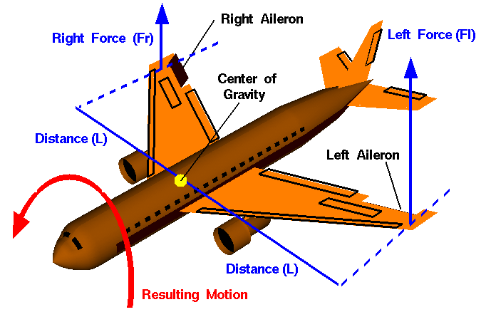
You may have realised that when the right aileron is raised not only will this destroy some lift but it will also cause drag. This unwanted drag causes the aircraft to rotate slightly in a clockwise direction and is referred to as adverse yaw. It is minimal in modern airliners as there are ways to mitigate this drag imbalance.
Rudder
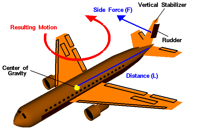
Rudders are situated at the rear of the vertical fin, or vertical stabiliser. The pilot will control these devices often with a pedal in the cockpit. In older aircraft the flight control surfaces would all be mechanically linked to the controls but this will not be the case in modern aircraft and the rudder will operate similar to the flaps and ailerons. The vertical stabiliser prevents side-to-side, or yawing motion of the aircraft nose. The rudder is the small moving section at the rear of the stabiliser that is attached to the fixed sections by hinges. Because the rudder moves, it varies the amount of force generated by the tail surface and is used to generate and control the yawing motion of the aircraft.
The rudder works by changing the effective shape of the aerofoil section on the stabiliser, if we consider it as a normal wing rotated 90 degrees, then moving the rudder to the left will increase the force going to the right (just as a flap would increase lift in a downwards position) This side force would act through the aerodynamic centre of the stabiliser and causes a moment around the centre of gravity of the aircraft, in this case rotating the aircraft anti clockwise, or with negative yaw around the vertical axis. Deflection of a rudder pedal causes a corresponding rudder deflection in the same direction; that is, pushing the left rudder pedal will result in a rudder deflection to the left. This, in turn, causes the rotation about the vertical axis moving the aircraft nose to the left, as shown below.
Elevator
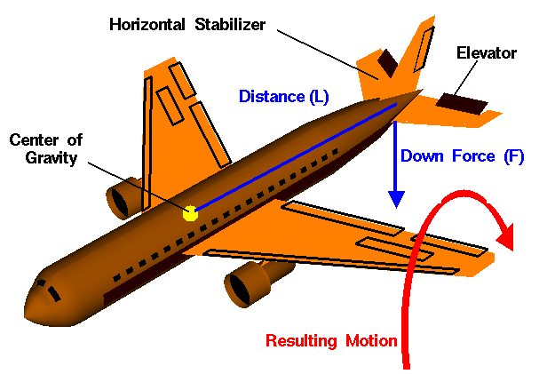
The elevators are situated on the trailing edge of the horizontal tail section. They are again hinged control surfaces controlled by hydraulic actuators. Opposite to the ailerons, these devices will work together by deflecting in the same direction on the right and left hand side. They work similarly to the other control surfaces in that they change the effective shape of the aerofoil section they are attached to.
The pilot will control the ailerons by pulling back on the stick or pushing it forward. Pulling back on the stick has the effect of raising the elevators. Once the elevators are raised this will decrease the lift generated by the horizontal tail section and cause the aircraft to rotate around the centre of gravity along the lateral axis. In this case the aircraft will be rotating nose up, so we can say pulling back on the controls will cause positive pitch. When the controls are pushed forwards the opposite occurs and more lift is generated as the elevators move down and the aircraft will pitch negatively, or nose down.
Spoilers
Spoilers are devices that extend upwards from the wing surface via hydraulic actuators. Spoiler controls can be used for roll control (outboard or mid-span spoilers) or descent control (inboard spoilers). Some aircraft use spoilers in combination with or in lieu of ailerons for roll control, primarily to reduce adverse yaw when rudder input is limited by higher speeds.

Interested in our Aerospace Engineering Courses?
At iLearn Engineering®, we offer a diverse range of online accredited aerospace engineering courses and qualifications to cater to different academic and career goals. Our aerospace courses are available in varying credit values and levels, ranging from 40 credit Engineering Diplomas to a Bachelor’s equivalent 360 credit International Graduate Diploma.
All Aerospace Engineering Courses
All Aerospace Engineering Diploma Courses can be seen here.
Short Aerospace Courses (40 Credits)
- Diploma in Aerospace Engineering
- Diploma in Aircraft Design
- Diploma in Principles of Flight
- Diploma in Aerospace Structures
- Diploma in Aerodynamics
- Diploma in Aerodynamics, Propulsion and Space
First Year of Undergraduate (Level 4 – 120 Credits)
Higher International Certificate in Aerospace Engineering
Years One and Two of Undergraduate (Level 5 – 240 Credits)
Higher International Diploma in Aerospace Engineering
Degree Equivalent International Graduate Diploma (Level 6 – 360 Credits)
International Graduate Diploma in Aerospace Engineering
Complete Engineering Course Catalogue (all courses)
Alternatively, you can view all our online engineering courses here.
Recent Posts
Civil Engineering Courses and Diplomas: Topics, Skills and Career Routes
Civil Engineering Courses and Diplomas: Topics, Skills and Career Routes Introduction Civil engineering is the backbone of modern society. From roads and bridges to skyscrapers and water systems, civil engineers design, build, and maintain the infrastructure that keeps the world running. If you’re considering a civil engineering course or diploma, understanding what it covers is […]
What Is a Diploma in Engineering? Courses, Levels and Career Routes Explained
What Is a Diploma in Engineering? Courses, Levels and Career Routes Explained Introduction Engineering shapes the world around us, from the buildings we live in to the technology we use every day. But for many aspiring engineers, the biggest question is not whether to pursue engineering, but how to start. Traditional university degrees are not […]
Engineering Courses: How to Choose the Right Route for Your Career
Engineering Courses: How to Choose the Right Route for Your Career Introduction Choosing an engineering course can feel like standing at the beginning of several different roads, each leading towards a different kind of future. One route may lead into mechanical systems and manufacturing. Another may lead towards aircraft, infrastructure, electronics, computing, renewable energy or […]