Evaluating Aircraft Performance During Climb
Introduction
The climb phase is one of the most critical segments of flight, where aircraft performance, safety, and efficiency are closely interlinked. During this phase, pilots and engineers must carefully evaluate key performance parameters such as climb rate, airspeed, thrust, altitude gain, and fuel consumption. Understanding how these variables interact provides valuable insight into aircraft capability, engine performance, and operational limits.
This blog explores the essential parameters used to evaluate aircraft performance during climb and explains their significance in flight analysis and engineering applications.
Forces in Climb
We will start by considering the forces which act upon the aircraft, where the power necessary for this manoeuvre originates, performance and rate of climb. Let us first consider the diagram below which figure shows the forces acting upon the aircraft during a climb.
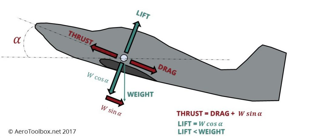
We can generate two equations from this diagram for thrust and lift:
T = D + W sin ∝
L = W cos ∝
What the first equation can tell us about the thrust required for the aircraft to climb in such a way is that the thrust must overcome the drag, D, and a component of weight, W sin cos ∝. The weight component will increase as the angle of climb, ∝, also increases. More thrust is therefore required to climb at steeper angles.
Whilst that first result is perhaps unsurprising, if we analyse the second equation we can see that as ∝ increases the value of cos ∝ will decrease. This implies that the lift generated will decrease with the climb angle. This result is surprising as the overall effect of a climb is to increase altitude, it is however, the vertical component of thrust that is primarily responsible for the upwards movement of the aircraft.
For most typical commercial aircraft a typical climb angle will be around 15 to 20 degrees and generally will not exceed these values.
Example: Calculate the lift and thrust from an aircraft if the aircraft is in steady climb at 15 degrees to the horizontal. The aircraft has a mass of 5000kg and you can assume the drag to be 6kN.
Solution:
T = D + W sin ∝ and W = mg
T = 6000 + ( 5000 x 9.81) sin 15
T = 18695 N
L = W cos ∝ and W = mg
L = ( 5000 x 9.81) cos 15
L = 47379 N
Power Curves
A more practical way of approaching climbing problems for aircraft is to examine power, or performance curves. As when the aircraft enters a climb excess power is required for this manoeuvre. The curves show estimated power required by the engine (in this case propeller) for level flight at various speeds, the power available from the engine considering inefficiencies and an indication of the maximum power available for climb. The curves enable forecasts to be made of the probable performance of the aircraft. A typical power curve for a turbo-prop is given below.
The curve indicating the initial power output of the engine, or the power delivered to the engine by propeller, is selected through a more thorough analysis but for simplicity sake is already selected. This curve depends upon operating parameters of the gas turbine engine. From this a second curve can be generated below that represents the actual power available from the propeller after considering inefficiencies. A typical propeller will have a propulsive efficiency of around 80%. The power required can then be found by finding the distance between the curves at specific air speeds.
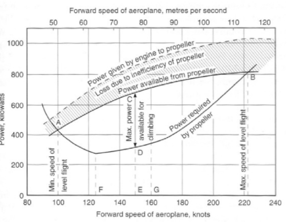
The chart above represents power curves for an aircraft that has an approximate drag of 4200N. This drag will have been calculated from combining the form drag and induced drag. General methods would include measuring the drag of a scale model in a wind tunnel and then scaling up the results to account for the full size aircraft.
A mathematical way of calculating the power required from the drag is to use the equation below, where D is drag and V is the airspeed:
P = DV
and hence for our example at an airspeed of 78m/s power required is:
P = 4200 x 78 = 328kW
This is approximately equal to the point D drawn on the diagram above at the indicated airspeed. The power available for climb is then found from the length of line BC, roughly 300kW.
Effects of Altitude
An important factor to consider with the power curves is the current altitude of the aircraft and how this affects the curves.
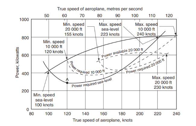
The chart shows what effect on performance increasing altitude has. As the altitude increases the air density will decrease. The only way in which to support the aircraft weight whilst maintaining lift is to increase the speed and maintain dynamic pressure.
This means the aircraft needs to fly at the same indicated airspeed, indicating the drag will not change. This seems like flying at higher altitudes is advantageous as higher speeds can be reached without increasing drag, however, problems arise from the propulsive systems – they are summarised below:
- Power required is a sum of speed and drag, meaning as speed increases so does power required.
- The power output of piston engines falls as air density reduces.
- An increased speed is required to maintain lift and drag, this requires faster propeller speeds. This causes problems associated with flow over the blades.
- At high altitudes the cockpit and cabin must be pressurised adding to complexity and weight of the aircraft.
- As height and speed increase compressibility effects are encountered across the propeller.
The diagram also shows us that at increasing altitudes the power available from the engine decreases and the power required increases. This causes the curves to become close together meaning there is an increase in minimum speed and a decrease in maximum. It is important to note that the rate of climb will also be decreasing.
Rate of Climb
To look at altitude changes we need to think in terms of energy changes. In climb we are turning kinetic and internal (engine) energy into an increase in potential energy. The engine provides the necessary energy for climb and the engine energy output per unit time is power (work per unit time). We are aware that a certain amount of power is required for straight and level flight at a given speed. To climb at that same speed then requires extra power and the amount of that extra power will determine the rate at which climb will occur.
The maximum rate of climb at a given speed will then depend on the difference between the power available from the engine at that speed and the power required for straight and level flight. This can be determined from the power curves mentioned above.
To consider how to calculate the rate of climb in an aircraft let us consider the governing equations for aircraft in climb:
T = D + W sin ∝
L = W cos ∝
If we examine the first equation we can manipulate as follows;
T – D = W sin ∝
(T-D) / W = sin ∝
(TV-DV) / W = V sin ∝
This expression is most useful for us as it allows us to generate the rate of climb V sin ∝
The equation gives the rate of climb in terms of TV and DV, these expressions are equal to the available and required power respectively. The term (TV – DV) is sometimes referred to as the excess power. When dividing by the weight the left hand side of the equation below is therefore specific excess power and is equal to the rate of climb:
(TV-DV) / W = V sin ∝
Example: An aircraft of mass 5000kg is powered by an engine capable of producing 1500kW of power. Calculate the maximum angle of climb at an air speed of 70 m/s if the efficiency of the propeller is 80%, and the drag at this speed is 6.7kN. In addition, calculate the rate of ascent.
This solution requires a few steps. Firstly,
The engine can produce 1500kW of power, 80% of this is available. Therefore the available power is (1500 x 0.8) = 1200kW.
We can use the formula:
(TV-DV) / W = V sin ∝
Where TV is the available power, 1200kW.
and W is the weight (5000 x 9.81) = 49050N
It is necessary to divide by V and find the arcsin of the result to get the climb angle, alpha.
sin-1 ( TV-DV)/WV = ∝
sin-1 (1200000 – ( 6700 x 70)) /( 49050 x 70) = ∝
∝ = sin-1 ( 0.213)
∝ = 12.3º
Now we have the climb angle we can find the rate of climb given by:
V sin ∝
V sin ∝ = 70 sin (12.3) = 14.9m/s
Interested in our Aerospace Engineering Courses?
At iLearn Engineering®, we offer a diverse range of online accredited aerospace engineering courses and qualifications to cater to different academic and career goals. Our aerospace courses are available in varying credit values and levels, ranging from 40 credit Engineering Diplomas to a Bachelor’s equivalent 360 credit International Graduate Diploma.
All Aerospace Engineering Courses
All Aerospace Engineering Diploma Courses can be seen here.
Short Aerospace Courses (40 Credits)
- Diploma in Aerospace Engineering
- Diploma in Aircraft Design
- Diploma in Principles of Flight
- Diploma in Aerospace Structures
- Diploma in Aerodynamics
- Diploma in Aerodynamics, Propulsion and Space
First Year of Undergraduate (Level 4 – 120 Credits)
Higher International Certificate in Aerospace Engineering
Years One and Two of Undergraduate (Level 5 – 240 Credits)
Higher International Diploma in Aerospace Engineering
Degree Equivalent International Graduate Diploma (Level 6 – 360 Credits)
International Graduate Diploma in Aerospace Engineering
Complete Engineering Course Catalogue (all courses)
Alternatively, you can view all our online engineering courses here.
Recent Posts
Civil Engineering Courses and Diplomas: Topics, Skills and Career Routes
Civil Engineering Courses and Diplomas: Topics, Skills and Career Routes Introduction Civil engineering is the backbone of modern society. From roads and bridges to skyscrapers and water systems, civil engineers design, build, and maintain the infrastructure that keeps the world running. If you’re considering a civil engineering course or diploma, understanding what it covers is […]
What Is a Diploma in Engineering? Courses, Levels and Career Routes Explained
What Is a Diploma in Engineering? Courses, Levels and Career Routes Explained Introduction Engineering shapes the world around us, from the buildings we live in to the technology we use every day. But for many aspiring engineers, the biggest question is not whether to pursue engineering, but how to start. Traditional university degrees are not […]
Engineering Courses: How to Choose the Right Route for Your Career
Engineering Courses: How to Choose the Right Route for Your Career Introduction Choosing an engineering course can feel like standing at the beginning of several different roads, each leading towards a different kind of future. One route may lead into mechanical systems and manufacturing. Another may lead towards aircraft, infrastructure, electronics, computing, renewable energy or […]