Inside the Turn: Understanding Key Flight Parameters
Introduction
This blog will focus on aircraft performing turning manoeuvres, in particular, the forces acting upon the aircraft and how the turning action changes these forces. We will discuss the idea behind load factors and consider how the airspeed of the aircraft will change during these manoeuvres.
If we consider an aircraft flying in steady level flight then there will be no turning motion.
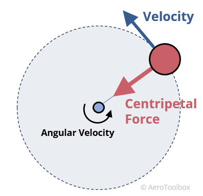
Once the aircraft begins to change its direction of flight there will always be some acceleration experienced, as the aircraft will have a curved flight path and essentially will enter into a turning manoeuvre. If we consider the idea of circular motion, then any object entering this type of motion must be experiencing an acceleration.
As velocity has both magnitude and direction, changing either one of these values will cause a change in velocity – which by definition is acceleration. In the case of circular motion, speed can remain the same but the constant changing of direction in circular motion causes the change in velocity. With this acceleration comes a centripetal force acting inwards, towards the centre of the turn.
We can calculate the magnitude of the centripetal force acting on an aircraft in a turn where the magnitude of velocity remains constant, that is the speed of the aircraft. You may recall that in circular motion acceleration is given by:
a = v2 /r , also F = ma
So
F = mv2 /r
But m =W/g
Combining these gives
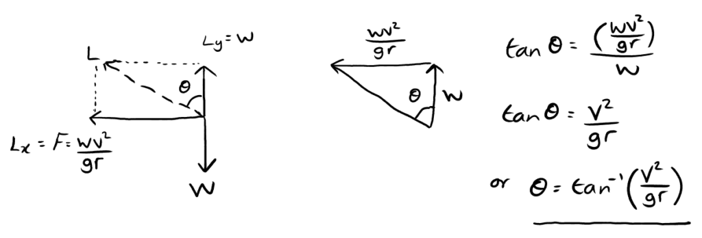
F = Wv2 / gr
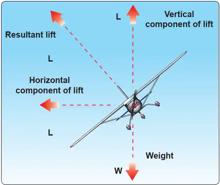
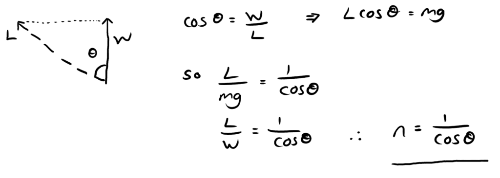
Now we can consider the balance of forces in the diagram above. If the aircraft is banked at an angle 𝛳 to the horizontal and this angle is such that the aircraft will have no tendency to slip inwards or outwards, then the lift will be acting perpendicular to the wings. The lift will provide a vertical component depending on the weight of the aircraft and an inwards force equal to the centripetal force. Below shows how we can consider forces to get the bank angle.
Example:
i) What is the correct angle of bank for an aircraft of mass 1100kg in a 500m turn at 90 knots?
ii) What would be the effect if the velocity were doubled?
iii) What would be the effect if the radius of the turn were halved?
iv) Which of these two parameters has the greatest effect on the bank angle and why?
Where 1 knot = 0.514 m/s
Solution: Firstly convert knots to m/s so:
v = 90 x 0.514 = 46.26m/s
i) θ = tan -1 ( v2/gr)
θ = tan -1 ( 46.262/9.81×500)
θ = 23.6º
ii) Doubling the velocity would change the calculation to:
θ = tan-1 ( 92.522/9.81×500)
θ = 60.2º
iii) halving the radius
θ = tan-1 ( 46.262/9.81×250)
θ = 41.1º
iv) Doubling the velocity increases the required bank angle by 36.6 degrees whilst halving the turn radius increases the required bank angle by 17.5 degrees. The effect of increasing velocity is more profound as the bank angle is proportional to the square of velocity whilst it is inversely proportional to the turn radius.
Loads During a Turn
It will be clear from the figures that the lift on the wings during the turn is greater than during straight flight; it is also very noticeable that the lift increases considerably with the angle of bank. The value of lift must be increased as we are depending solely on the vertical component of lift to balance the weight. This means that structural components, such as the wing spars, will have to carry loads considerably greater than those of straight flight. Mathematically we can deduce an expression for lift on the wings:
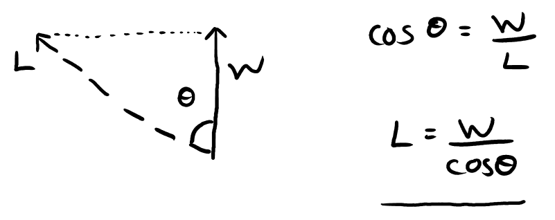
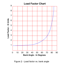
As L = W / cos θ we can clearly see for bank angles increasing from 0º to 90º, this will also cause the lift acting on the wings to increase. In fact as the bank angle reaches a value of 84º we can see that the lift is given by:
L = W / cos 84 = W / 0.1 = 10W
Compared to level flight where L = W, this is up to a 10 fold increase in the Lift force acting upon the aircraft. In fact, for aircraft this increase in load is often referred to as the load factor. For the example above we have just seen that for 84º bank angle L = 10W. The load factor is simply an expression of the lift divided by the weight so in this case, the load factor, n = L/W = 10. The load factor is 10 for this manoeuvre. The symbol n is used to denote load factor.
At 45°, the load factor increases to 1.4G. At a 60° bank angle, the load factor further increases to a value of 2. It is clear that the load factor changes with the bank angle, and to be more precise, it changes exponentially when the angle increases. At steep turns, there is more chance to attain maximum load factors. The graph shows load factor vs. angle of bank.
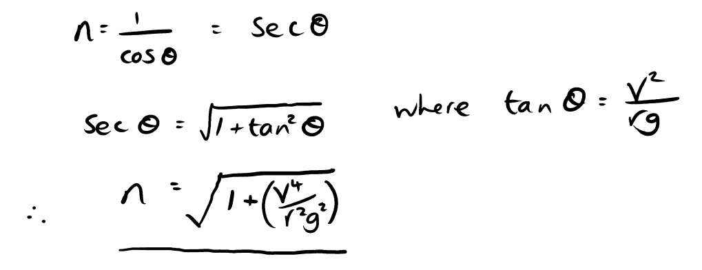
We can come up with a mathematical expression for load factor in terms of the bank angle.
This is a convenient way of finding the load factor n from a given bank angle. It should be noted here that the load factor is expressed in units of ‘g’ that is to say a load factor of 2 has the effect of doubling the forces acting upon it, as would doubling the effect of gravity, g. Note also that the load factor is exactly that, a factor, and does not actually possess units. This can also be seen in the above proof where:
n = L / W
If required we can express the load factor in terms of airspeed, turn radius and gravity. By using some algebraic manipulation and trigonometric identities this is provided below:
Example: If an aircraft is in a turn of radius 400m with an airspeed of 95 m/s. Determine the load factor.
Solution: We can deduce the bank angle from:
θ = tan-1 ( 952 / 9.81×400)
θ = 66.5º
The load factor n is given by:
n = 1/ cos θ
n = 1/ cos 66.5
n = 2.5
We can also read this from the graph above
With the change of load factor with the bank angle, aircraft stall speed increases. Stalling speed is where the aircraft wings no longer generate lift due to flow separation of turbulent air. The following proof results in an equation that shows that accelerated stalling speed (altered stalling speed due to load factor change) is proportional to the square root of the load factor.
If we rearrange the standard lift equation for velocity at max CL
vs = √ ( 2mg/ ρScLmax)
However, in banked flight L ≠ mg
But instead Lcos θ = mg
So L = mg /cos θ
Combining these equations, we can find the stall speed in a bank, vsb, in terms of the stall speed in a straight flight, vs, and bank angle θ
vsb = vs / √ cos θ
Or finally in terms of load factor stall speed is given by:
vsb = vs √n
Example: An aircraft with a mass of 6000kg is performing a banked turn at 30º. The air density at the current altitude is 1.1kgm-3 The maximum lift coefficient is 1.2 and the aircraft has a wing area of 16m2 . Find the stall speed in the banked turn.
Solution: We can find the stall speed in normal flight by rearranging the lift equation to give:
vs = √ ( 2mg/ ρScLmax)
vs = √ ( 2x6000x9.81/1.1x16x1.2)
vs = 76.7m/s
The load factor can be calculated from the bank angle with:
n = 1/ cos θ
n = 1 / cos 30 = 1.15
Finally stall speed in the turn is given by:
vsb = vs √n
vsb = 76.7 √1.15 = 82.3m/s
Aerodynamic forces such as wind gusts that will deflect the aeroplane from a straight line produce stress on the aeroplane structure. This alters the lift-to-weight ratio or the load factor. Aircraft are designed within specific safety margins and assumed maximum load factors within operation. Performing extreme manoeuvres and exceeding these design load factors may increase the stress within the structure of the aircraft and possibly exceed the safety factor, causing structural failure.
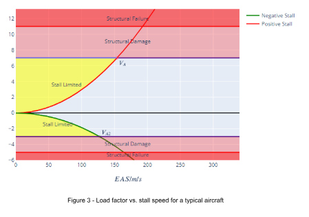
As we saw in the calculations above, stall speed will depend upon specific parameters of the aircraft such as weight (mass), lift coefficient and wing area. The figure above is a chart which depicts how positive and negative load factors affect an aircraft. They are often referred to as V-n diagrams. For this example the weight is considered to be 53 kN, wing area is 16m2 and the max lift coefficient is 1.6. The parameters are similar to the worked example on the above page. We previously calculated that for a bank angle of 30º, this equated to a load factor of 1.15. This in turn led to a stall speed of 82.3 m/s. This is the minimum speed required to produce lift for flight, if an aircraft were to fall below the stall speed it would produce insufficient lift for flight.
The intersection of the stall boundary and the limit load defines vA , the manoeuvre speed. Sometimes this is called the corner speed.
At speeds below vA fore/aft motion of the stick cannot produce enough load for structural damage to occur as the flow will separate before reaching an incidence at which nl will occur, where nl is the load factor at which permanent structural damage will occur. Hence at speeds below vA the aircraft is stall limited. Hence vA is the highest speed for safe application of maximum control deflection, whereas at speeds above vA the controls inputs must be limited to avoid overloading the airframe. A key point to notice is the negative load factor has a larger impact on stall speed, for instance, a load factor of 4 has a stall speed of 120 m/s and a load factor of -4 would be causing structural damage and a stall speed of 150m/s.
Interested in our Aerospace Engineering Courses?
At iLearn Engineering®, we offer a diverse range of online accredited aerospace engineering courses and qualifications to cater to different academic and career goals. Our aerospace courses are available in varying credit values and levels, ranging from 40 credit Engineering Diplomas to a Bachelor’s equivalent 360 credit International Graduate Diploma.
All Aerospace Engineering Courses
All Aerospace Engineering Diploma Courses can be seen here.
Short Aerospace Courses (40 Credits)
- Diploma in Aerospace Engineering
- Diploma in Aircraft Design
- Diploma in Principles of Flight
- Diploma in Aerospace Structures
- Diploma in Aerodynamics
- Diploma in Aerodynamics, Propulsion and Space
First Year of Undergraduate (Level 4 – 120 Credits)
Higher International Certificate in Aerospace Engineering
Years One and Two of Undergraduate (Level 5 – 240 Credits)
Higher International Diploma in Aerospace Engineering
Degree Equivalent International Graduate Diploma (Level 6 – 360 Credits)
International Graduate Diploma in Aerospace Engineering
Complete Engineering Course Catalogue (all courses)
Alternatively, you can view all our online engineering courses here.
Recent Posts
Civil Engineering Courses and Diplomas: Topics, Skills and Career Routes
Civil Engineering Courses and Diplomas: Topics, Skills and Career Routes Introduction Civil engineering is the backbone of modern society. From roads and bridges to skyscrapers and water systems, civil engineers design, build, and maintain the infrastructure that keeps the world running. If you’re considering a civil engineering course or diploma, understanding what it covers is […]
What Is a Diploma in Engineering? Courses, Levels and Career Routes Explained
What Is a Diploma in Engineering? Courses, Levels and Career Routes Explained Introduction Engineering shapes the world around us, from the buildings we live in to the technology we use every day. But for many aspiring engineers, the biggest question is not whether to pursue engineering, but how to start. Traditional university degrees are not […]
Engineering Courses: How to Choose the Right Route for Your Career
Engineering Courses: How to Choose the Right Route for Your Career Introduction Choosing an engineering course can feel like standing at the beginning of several different roads, each leading towards a different kind of future. One route may lead into mechanical systems and manufacturing. Another may lead towards aircraft, infrastructure, electronics, computing, renewable energy or […]