What Really Keeps an Aircraft Flying?
Introduction
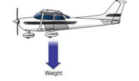
In this blog we will identify the four main forces concerned with aircraft in flight. We will discuss the nature of these forces and deduce mathematical and descriptive definitions. If an aircraft is to be considered in straight and level flight then it will not be gaining altitude, rolling or yawing. It will be maintaining a constant airspeed, altitude and heading. If we were to consider the forces acting on the aircraft it would look something similar to the diagram below.
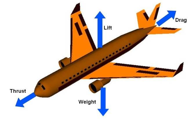
The four forces we will consider are lift, drag, thrust and weight.
Lift and Drag
Lift and drag are important forces that act upon bodies in a fluid flow, in this case our fluid is air. Firstly it is important to define these forces, we will then examine the mathematical formulas that describe them.
Lift
Lift is a force that acts perpendicular to the relative motion of the airflow and acts through the aerodynamic centre (centre of pressure) of the wing. It is a result of different pressure on two sides of an object, if there is a greater pressure on the underside, lift will be positive and there will exist an upwards force. Perhaps the best object to illustrate this is an aerofoil section moving through a fluid.
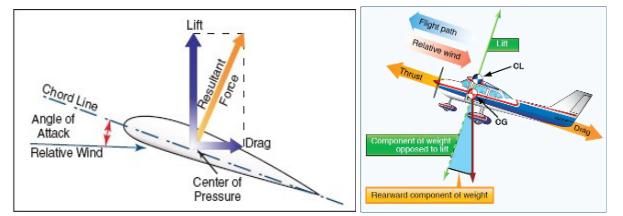
The diagram above demonstrates that the lift is perpendicular to the relative airflow, in straight and level flight this force will be acting upwards and directly opposing weight. The magnitude of the lift force will depend upon a few key factors and for a wing those factors are the relative velocity between wing and air flow, or air speed, the density of the air, wing area and lift coefficient of the wing. All of these values can vary throughout the course of flight. For example, air becomes less dense with altitude, airspeed can be varied and changing the profile of a wing surface and area can be achieved with flaps and slats.
The lift coefficient of an aerofoil depends on a number of parameters but perhaps the most important is the camber, or curvature of the section. Lift is a vector quantity that has magnitude and direction, as discussed it always acts perpendicular to the motion. The position of this force is always at a location called the aerodynamic centre of the wing – the part of the wing where all forces are considered to act.
Mathematically we can give the lift force as:
L= ½ ρV2ScL
Where; ρ = density ( kgm-3), V = velocity ( ms-1), S = wing area (m2), CL = lift coefficient ( no units), L = lift (N)
Example 1. If a Boeing 747 has a wing area of 510m2 and is cruising at 263 ms-1 , the density of the air is 1.20 kgm-3 , and the lift coefficient is 0.6, what is the lift Force generated?
Solution: The most important thing is to check all unit are in SI, in this case they are so we can input them directly into the lift equation
L= ½ ρV2ScL
L = ½ x 1.2 x 2632 x 510 x 0.6
Lc = 12.7MN
Example 2: An aircraft weighs 125,000kg, has a wing area of 145m2, the density of the air is 1.20 kgm-3 and the lift coefficient is 0.52. Find the airspeed the aircraft must be travelling with to be in level flight.
Solution: If the aircraft is in level flight the lift must equal the weight. The weight is:
W = mg
W = 125000 x 9.81 = 1.23MN
So L = 1.23 MN
L= ½ ρV2ScL
Rearranging to find velocity gives:
V = √2L / ρScL = √ 2×1.23×106 / 1.2×1.45×0.52
V = 165m/s
Drag
Drag is a mechanical force that is caused by the difference in velocity between the aircraft and the velocity of the fluid it is moving through (air).
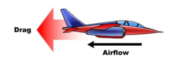
For drag to be generated, the solid body must be in contact with the fluid. If there is no fluid, there is no drag. As drag is a force it is a vector quantity, similar to lift. A vector quantity will have a magnitude and a direction. Drag always opposes the motion of the aircraft. The equation that governs drag for a surface moving through a fluid is similar to that of lift. However it is slightly more complex and various factors can influence drag, such as:
- Body shape
- Velocity of air
- Turbulence of air
- Surface roughness of body
- Angle of attack of the body
- Air density
The drag formula is presented below:
D = ½ ρV2ScD
Where CD is the drag coefficient. There now exists a drag coefficient which determines the amount of drag a body will experience, this is made up of more complex interaction and accounts for various types of drag.
One of the sources of drag is the skin friction between the molecules of the air and the solid surface of the aircraft. Because the skin friction is an interaction between a solid and a gas, the magnitude of the skin friction depends on properties of both solid and gas. For the solid, a smooth, waxed surface produces less skin friction than a roughened surface. For the gas, the magnitude depends on the viscosity of the air and the relative magnitude of the viscous forces to the motion of the flow.
We can also think of drag as aerodynamic resistance to the motion of the object through the fluid. This source of drag depends on the shape of the aircraft and is called form drag. As air flows around a body, the local velocity and pressure are changed. Since pressure is a measure of the momentum of the gas molecules and a change in momentum produces a force, a varying pressure distribution will produce a force on the body.
There is an additional drag component caused by the generation of lift. Aerodynamicists have named this component the induced drag. It is also called “drag due to lift” because it only occurs on finite, lifting wings. Induced drag occurs because the distribution of lift is not uniform on a wing, but varies from root to tip
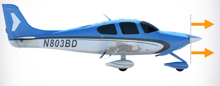
Notice that the area S, given in the drag equation is given as a reference area. The drag depends directly on the size of the body. Since we are dealing with aerodynamic forces, the dependence can be characterised by some area.
But which area do we choose? If we think of drag as being caused by friction between the air and the body, a logical choice would be the total surface area of the body. If we think of drag as being a resistance to the flow, a more logical choice would be the frontal area of the body that is perpendicular to the flow direction.
Finally, if we want to compare with the lift coefficient, we should use the same wing area used to derive the lift coefficient. Since the drag coefficient is usually determined experimentally by measuring drag and the area and then performing the division to produce the coefficient, we are free to use any area that can be easily measured. If we choose the wing area, rather than the cross-sectional area, the computed coefficient will have a different value. But the drag is the same, and the coefficients are related by the ratio of the areas. In practice, drag coefficients are reported based on a wide variety of object areas. In the report, the aerodynamicist must specify the area used; when using the data, the reader may have to convert the drag coefficient using the ratio of the areas.
Example: In a wind tunnel the drag force on a model wing section is measured to be 120 N. The wing section being analysed was stationary with air at 50 m/s being passed over it. The density of air is standard at sea level and is 1.23 kgm-3. Calculate the drag coefficient of this aerofoil section if the area in contact with the flow is 0.4m2 .
D = ½ρV2ScD
CD = 2D /ρV2S = 2×120 / 1.23 x 502 x 0.4
CD = 0.195
Aircraft usually relate these two key quantities together in something called the lift to drag ratio, which is simply the lift force divided by weight (or lift coefficient divided by drag coefficient)
Thrust and Weight
Thrust
Thrust is the force which moves an aircraft through the air. Thrust is used to overcome the drag of an aeroplane, and to overcome the weight of a rocket. Thrust is generated by the engines of the aircraft through some kind of propulsion system.
Thrust is a mechanical force, so the propulsion system must be in physical contact with a working fluid to produce thrust. Thrust is generated most often through the reaction of accelerating a mass of gas. Since thrust is a force, it is a vector quantity having both a magnitude and a direction. The engine does work on the gas and accelerates the gas to the rear of the engine; the thrust is generated in the opposite direction from the accelerated gas. The magnitude of the thrust depends on the amount of gas that is accelerated and on the difference in velocity of the gas through the engine.
In an aircraft, the thrust is generated in different ways according to the type of propulsion:
- Turbojet: all the thrust is generated in the form of jet efflux from the rear of the engine. (Now used mostly in military aircraft).
- Turbofan: most of the thrust is generated by a large fan at the front of the engine; a small percentage is generated by jet efflux.
- Turboprop: most of the thrust is generated by the propeller; a small percentage is generated by jet efflux.
- Piston: all the thrust is generated by the propeller.
The Power required to generate thrust depends on a number of factors, but in simple terms it may be said that the power is proportional to the thrust required multiplied by the aircraft speed.
Weight
The weight of the aircraft must be considered, it is important to note here that students often confuse weight with mass. The mass of an object is given in kilograms and is a scalar quantity. Weight is a force, measured in newtons, and must be equal to the mass multiplied by the acceleration due to gravity. The direction of the force is always downwards to the centre of the Earth. Just as lift, drag and thrust can all vary throughout the course of a flight so too can the weight. As fuel is burned the mass of the aircraft will decrease significantly.
The thrust can be divided by the weight at specific times to give a useful property called the thrust to weight ratio. This parameter is an important indicator and increases with the aerodynamic performance of an aircraft.
Aircraft Moments: How Rotation and Control Are Achieved in Flight
When an aircraft flies, it does not merely translate through the air under the action of forces such as lift and drag. It also rotates, changing its orientation in space. These rotations are caused by moments, which are the rotational effect of forces acting at a distance from the aircraft’s centre of gravity. In aircraft flight mechanics, moments are just as important as forces because they determine attitude, stability, and control.
A moment is defined as the product of a force and its perpendicular distance from a reference point, usually the centre of gravity:
M = F x d
Even a relatively small force can create a significant moment if it acts far from the centre of gravity. This is why tail surfaces, although smaller than wings, have such a strong influence on aircraft behaviour.
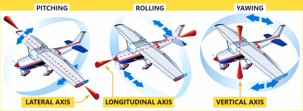
An aircraft rotates about three principal body axes that pass through its centre of gravity. Rotation about the lateral axis produces pitching motion, rotation about the longitudinal axis produces rolling motion, and rotation about the vertical axis produces yawing motion. Correspondingly, the aircraft experiences pitching, rolling, and yawing moments, each of which plays a distinct role in flight.
Pitching moment
The pitching moment controls whether the aircraft’s nose moves up or down. It is generated primarily by the lift distribution over the wing and by the force produced by the horizontal tail. Most cambered airfoils naturally produce a nose-down pitching moment as the angle of attack increases.
This behaviour is described using the non-dimensional pitching moment coefficient (Cm), and the pitching moment itself can be written as:
M = ½ ρV2ScCm
Here, ρ is the air density, V is the airspeed, S is the wing reference area, and c is the mean aerodynamic chord. For a statically stable aircraft, the overall pitching moment tends to restore the aircraft to its trimmed angle of attack after a disturbance. The horizontal tail usually provides this stabilising effect by generating a balancing moment about the centre of gravity.
Rolling Moment
Rolling motion occurs about the aircraft’s longitudinal axis and is governed by the rolling moment. This moment is intentionally generated using ailerons, which create a difference in lift between the left and right wings. The resulting rolling moment causes the aircraft to bank, enabling turns. The rolling moment can be expressed as:
L = ½ ρV2SbCI
where b is the wingspan and Cl is the rolling moment coefficient. Wing geometry also influences rolling behaviour. Features such as dihedral angle increase lateral stability by producing a restoring rolling moment when the aircraft is disturbed.
Yawing Moment
The yawing moment causes the aircraft’s nose to move left or right about the vertical axis. This moment is mainly controlled by the rudder and stabilised by the vertical tail. Yawing moments are especially important during asymmetric flight conditions, such as engine failure or crosswind operations. The yawing moment is given by:
N = ½ ρV2SbCm
Yaw and roll are strongly coupled in aircraft motion. For example, adverse yaw occurs when aileron deflection intended to produce roll also generates an unintended yawing moment. The vertical tail counters this effect and contributes to directional stability by aligning the aircraft with the relative airflow.
The relationship between moments and motion is governed by Newton’s second law for rotation:
Σ M = Iα
where I is the moment of inertia about the relevant axis and α is the angular acceleration. This equation shows that an aircraft’s resistance to rotational motion depends not only on the applied moment but also on how its mass is distributed.
Ultimately, aircraft moments determine how stable, controllable, and responsive an aircraft is. While forces decide whether an aircraft climbs, descends, or accelerates, moments decide how it points and how it responds to pilot or autopilot commands. A well-designed aircraft achieves a careful balance of moments to ensure safe, efficient, and predictable flight.
Interested in our Aerospace Engineering Courses?
At iLearn Engineering®, we offer a diverse range of online accredited aerospace engineering courses and qualifications to cater to different academic and career goals. Our aerospace courses are available in varying credit values and levels, ranging from 40 credit Engineering Diplomas to a Bachelor’s equivalent 360 credit International Graduate Diploma.
All Aerospace Engineering Courses
All Aerospace Engineering Diploma Courses can be seen here.
Short Aerospace Courses (40 Credits)
- Diploma in Aerospace Engineering
- Diploma in Aircraft Design
- Diploma in Principles of Flight
- Diploma in Aerospace Structures
- Diploma in Aerodynamics
- Diploma in Aerodynamics, Propulsion and Space
First Year of Undergraduate (Level 4 – 120 Credits)
Higher International Certificate in Aerospace Engineering
Years One and Two of Undergraduate (Level 5 – 240 Credits)
Higher International Diploma in Aerospace Engineering
Degree Equivalent International Graduate Diploma (Level 6 – 360 Credits)
International Graduate Diploma in Aerospace Engineering
Complete Engineering Course Catalogue (all courses)
Alternatively, you can view all our online engineering courses here.
Recent Posts
Civil Engineering Courses and Diplomas: Topics, Skills and Career Routes
Civil Engineering Courses and Diplomas: Topics, Skills and Career Routes Introduction Civil engineering is the backbone of modern society. From roads and bridges to skyscrapers and water systems, civil engineers design, build, and maintain the infrastructure that keeps the world running. If you’re considering a civil engineering course or diploma, understanding what it covers is […]
What Is a Diploma in Engineering? Courses, Levels and Career Routes Explained
What Is a Diploma in Engineering? Courses, Levels and Career Routes Explained Introduction Engineering shapes the world around us, from the buildings we live in to the technology we use every day. But for many aspiring engineers, the biggest question is not whether to pursue engineering, but how to start. Traditional university degrees are not […]
Engineering Courses: How to Choose the Right Route for Your Career
Engineering Courses: How to Choose the Right Route for Your Career Introduction Choosing an engineering course can feel like standing at the beginning of several different roads, each leading towards a different kind of future. One route may lead into mechanical systems and manufacturing. Another may lead towards aircraft, infrastructure, electronics, computing, renewable energy or […]