

Why Aircraft Engine Intakes Use Diffusers: Slowing Air to Recover Pressure
An aircraft engine needs a large, steady supply of air at its compressor face. That may sound simple, but the air approaching an aircraft is moving quickly, often with changes in direction, velocity and pressure caused by the aircraft’s shape and flight condition.
An intake diffuser helps manage this problem. It is a carefully shaped passage that increases in cross-sectional area, causing subsonic airflow to slow down while its static pressure rises. This process is called pressure recovery.
The important point is that a diffuser does not create energy or raise the airflow’s total pressure. Instead, it converts part of the air’s kinetic energy into static pressure while trying to minimise losses. A well-designed intake must therefore deliver air to the compressor with high total-pressure recovery, low distortion and minimal drag. [1]
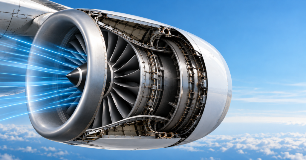
What is an aircraft intake diffuser?
An aircraft intake is the part of the engine installation that captures freestream air and guides it towards the compressor. In a gas-turbine engine, the inlet is upstream of the compressor and performs no thermodynamic work on the flow. Its purpose is aerodynamic: to deliver air in the condition the compressor needs. [1]
A diffuser is the section of duct where the flow area increases in the direction of travel. For subsonic air, increasing the area reduces velocity. In an ideal flow, the reduction in velocity is accompanied by an increase in static pressure.
This is useful because a compressor works most effectively when the incoming flow is as uniform as possible. If the intake sends highly uneven, swirling or separated airflow towards the compressor, the blades can experience rapidly changing conditions. That can reduce efficiency and, in severe cases, contribute to compressor stall or surge. [1]
Why a wider duct slows subsonic airflow
The continuity equation expresses conservation of mass. For steady incompressible flow:
ṁ = ρAV
Where:
- ṁ is mass flow rate in kg/s
- ρ is air density in kg/m³
- A is duct cross-sectional area in m²
- V is airflow velocity in m/s
If density remains approximately constant, the relationship simplifies to:
A₁V₁ = A₂V₂
In other words, if the flow area increases, velocity must decrease to pass the same amount of air through the duct each second.
This is the opposite of a converging nozzle in subsonic flow. A nozzle reduces area to accelerate the air; a diffuser increases area to decelerate it.
How slowing the airflow raises static pressure
For low-speed, approximately incompressible flow, Bernoulli’s equation links pressure, velocity and height:
P + ½ρV² + ρgz = constant
Where:
- P is static pressure
- ρ is air density
- V is velocity
- g is gravitational acceleration
- z is height
Within a short, near-horizontal intake passage, the height term is usually small. If velocity falls through a diffuser, the dynamic-pressure term, ½ρV², also falls. In an ideal situation, static pressure rises by a corresponding amount.
This is why the term pressure recovery is used. The diffuser is recovering static pressure from the kinetic energy already present in the approaching airflow.
However, this does not mean total pressure increases. Real airflow experiences viscous friction, boundary-layer growth, turbulence and possible separation. These effects reduce total pressure, which is why intake design is a balance between slowing the flow sufficiently and avoiding excessive losses.
A simple subsonic diffuser example
Consider an illustrative intake diffuser carrying air at a density of 1.20 kg/m³.
At the diffuser entrance:
- Area, A₁ = 0.30 m²
- Velocity, V₁ = 90 m/s
At the diffuser exit, the area increases to 0.45 m².
Using continuity:
A₁V₁ = A₂V₂
0.30 × 90 = 0.45 × V₂
V₂ = 60 m/s
The air therefore slows from 90 m/s to 60 m/s.
Using the simplified Bernoulli relationship, the ideal static-pressure rise is:
ΔP = ½ρ(V₁² − V₂²)
ΔP = ½ × 1.20 × (90² − 60²)
ΔP = 2,700 Pa
The calculated pressure rise is an ideal estimate. A real intake would recover less than this because some total pressure is lost through friction, surface roughness, curvature and any flow separation.
The calculation is still valuable because it shows the underlying engineering decision: duct geometry can be used to trade airspeed for static pressure before the compressor.
Why diffuser design is not simply “make it wider”
A sudden increase in duct area may slow the core flow, but it can also create an adverse pressure gradient. This means pressure rises in the direction of travel, forcing the slower-moving air close to the duct wall to move against increasing pressure.
If the boundary layer does not have enough momentum, it can separate from the wall. Instead of smooth attached flow, the duct develops recirculating regions, turbulence and an uneven velocity profile.
For an engine intake, the consequences can include:
- reduced total-pressure recovery;
- non-uniform flow at the compressor face;
- increased drag and aerodynamic losses;
- greater sensitivity to changes in angle of attack, sideslip or engine power setting; and
- a higher risk of compressor-operability problems.
A successful diffuser therefore needs more than the correct area ratio. Its length, divergence angle, surface condition, curvature and interaction with the aircraft’s external airflow all matter.
Pressure recovery, distortion and spillage drag
Engineers assess an intake by considering more than its static-pressure rise.
Total-pressure recovery
Total-pressure recovery compares the total pressure reaching the compressor with the total pressure available in the freestream. It indicates how much useful pressure has been retained after aerodynamic losses in the intake. NASA notes that recovery depends on factors including inlet shape, aircraft speed, engine airflow demand and manoeuvring condition. [1]
Flow distortion
The compressor does not merely need enough air; it needs air delivered evenly. If one region of the compressor face has lower pressure or velocity than another, the rotor blades encounter uneven aerodynamic loading as they rotate. Intake distortion can therefore affect both efficiency and compressor stability. [1]
Spillage drag
An intake is usually sized to meet the engine’s highest airflow demand. At other operating conditions, not all approaching air enters the intake. Some is diverted around the cowl lip, producing spillage drag. Intake design must balance capture area, drag, pressure recovery and the airflow required by the engine. [1]
Subsonic and supersonic intakes are different problems
This article focuses on subsonic diffusion, where increasing duct area slows the flow and can raise static pressure.
At supersonic speeds, the relationship between area and velocity changes. A converging passage can decelerate supersonic flow, and shock waves become a major source of total-pressure loss. Supersonic intakes are consequently designed to manage shocks as well as diffusion, often using carefully positioned ramps, cones or variable geometry.
The underlying objective remains the same: deliver suitable air to the compressor with the lowest practical losses. The aerodynamic methods required to achieve it are different.
From airflow equations to propulsion performance
Continuity and Bernoulli’s equation provide a useful first explanation of why a subsonic aircraft intake diffuser widens. They show how a reduction in velocity can support a rise in static pressure.
In engineering practice, that is only the starting point. The intake must also avoid separation, preserve total pressure, limit flow distortion and work across changing flight and engine conditions.
For a related example of how pressure data is used to investigate airflow around aerospace components, see How Wind Tunnels Use Pressure Measurements to Test Aircraft Aerodynamics. Learners who want to study airflow, propulsion and high-speed flight in more depth can explore the Diploma in Aerodynamics, Propulsion and Space.
Frequently asked questions
Does a diffuser increase an engine’s total pressure?
No. A passive diffuser does not add energy to the airflow. It converts some velocity into static pressure, while real aerodynamic losses reduce total pressure.
Why does flow separation matter in an intake diffuser?
Separation creates turbulence and uneven airflow, reducing pressure recovery and potentially delivering distorted flow to the compressor.
Is every aircraft engine intake a simple widening duct?
No. Intake geometry depends on the engine type, aircraft layout and flight regime. Subsonic, transonic and supersonic intakes each require different aerodynamic solutions.
References
[1] NASA Glenn Research Center, “Inlet Performance”
Interested in our Aerospace Engineering Courses?
At iLearn Engineering®, we offer a diverse range of online accredited aerospace engineering courses and qualifications to cater to different academic and career goals. Our aerospace courses are available in varying credit values and levels, ranging from 40 credit Engineering Diplomas to a Bachelor’s equivalent 360 credit International Graduate Diploma.
All Aerospace Engineering Courses
All Aerospace Engineering Diploma Courses can be seen here.
Short Aerospace Courses (40 Credits)
- Diploma in Aerospace Engineering
- Diploma in Aircraft Design
- Diploma in Principles of Flight
- Diploma in Aerospace Structures
- Diploma in Aerodynamics
- Diploma in Aerodynamics, Propulsion and Space
First Year of Undergraduate (Level 4 – 120 Credits)
Higher International Certificate in Aerospace Engineering
Years One and Two of Undergraduate (Level 5 – 240 Credits)
Higher International Diploma in Aerospace Engineering
International Graduate Diploma (Level 6 – 360 Credits)
International Graduate Diploma in Aerospace Engineering
Complete Engineering Course Catalogue (all courses)
Alternatively, you can view all our online engineering courses here.
Recent Posts
Why There Is No Perfect Aerofoil: The Design Trade-Offs Behind Every Aircraft Wing
Why There Is No Perfect Aerofoil: The Design Trade-Offs Behind Every Aircraft Wing If a designer could create a perfect aerofoil, it would produce very high lift with almost no drag, remain stable at every angle of attack, fit a lightweight structure inside the wing and work equally well at low and high speed. No […]
How Aerofoils Generate Lift: A Beginner’s Guide to Angle of Attack, Camber and Pressure Distribution
How Aerofoils Generate Lift: A Beginner’s Guide to Angle of Attack, Camber and Pressure Distribution An aerofoil does not create lift simply because its upper surface is curved. Lift is produced because the aerofoil meets the airflow at a suitable angle and shape, causing a pressure distribution that results in an aerodynamic force. For aircraft […]
How Wind Tunnels Use Pressure Measurements to Test Aircraft Aerodynamics
How Wind Tunnels Use Pressure Measurements to Test Aircraft Aerodynamics Before an aircraft, wing or engine intake is built at full scale, engineers need evidence of how air will move around it. A wind tunnel provides that evidence by moving controlled airflow past a model and measuring the pressure, forces and flow behaviour that result. […]