

Evaluating the slenderness ratio in columns.
Following on from our previous article on buckling failure modes, we’re going to dive deeper into the types of buckling in columns.
Column Buckling.
Column buckling, or column stability, can be expressed as the failure of load-bearing capacity cause by the effect of pressure. It’s manifested as bending, or buckling, of the column. You can see an example of it in the image below:
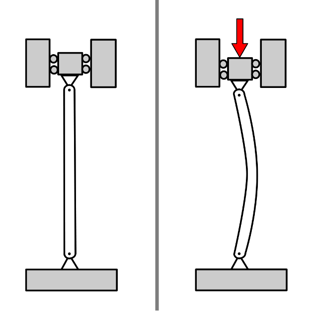
Types of Buckling in Columns
There are generally three types of buckling in columns:
- Flexural buckling.
- Torsional buckling.
- Flexural-torsional buckling.
You can also see an image showing these types of buckling in this image:

Flexural buckling
Flexural buckling is the buckling mode, which governs the design of a member in pure compression. For buckling calculation of the column, it is necessary to check the slenderness of the column.
Depending on the support conditions, material, and geometric characteristics of the column, it is possible to calculate the slenderness of the column.

Torsional buckling and flexural-torsional buckling
Torsional buckling is simply a twisting of the entire cross section about its shear centre.
Flexural-torsional buckling is a compression member instability involving a combination of member bending and twisting as well as any local buckling of slender elements. in this behavioural sense, it resembles lateral-torsional buckling of unbraced beams.

How can we calculate the length of the column?
The length of the column is calculated using the following expression:
Le=K L
Where:
- K: effective length coefficient depending on the support conditions
- L: length of the column (m).
Column slenderness is defined by the following expression:
λ=Leimin
Where are:
- Le – effective length of the column (m),
- imin – minimum radius of gyration, imin=IA (m),
- I – moment of inertia (m4),
- A – cross-section area (m2).
Let’s look at an example. Take a 3m long column, with on end pinned and the other fixed. Imagine it has a cross-section area of a = 3.125×10⁻³m2 and moment of inertia i = 4.7526×10⁻⁶m4.
We can calculate the column slenderness as:
Le=K·L=0.7·3.0m=2.1m
imin=IA=4.7526×10-60.003125=0.01233 m
λ=Leimin=2.1m0.01233m=170.3
Non-dimensional slenderness
Since the buckling occurs under compression of the column, material characteristics affect the buckling critical force. Due to that, EC3 defined non-dimensional slenderness by the following expression:
=1
Where are:
- λ – column slenderness,
- 1=π xEfy,
- E – Young modulus of elasticity (Pa),
- fy – steel yield strength (Pa).
The table below shows steel grade mechanical properties:

Let’s look at an example. Imagine a 3m long column with one end pinned and the other fixed. It has a cross-section area of a = 3.125×10⁻³ m2 and moment of inertia I=4.7526×10⁻⁶ m4.
We can calculate the column non-dimensional slenderness for steel grade S235 and E=210 x 109 Pa by:
Le=K x L=0.7×3.0m=2.1m
imin=IA=4.7526×10-60.003125=0.01233 m
λ=Leimin=2.1m0.01233m=170.3
1=π x Efy=3.14 x 210000 x 106 Pa235 x 106 Pa=29.9
=1=170.329.9=5.69
Keep an eye out for future courses on different types of buckling and various calculations around buckling in columns
Interested in our courses?
Interested in civil or mechanical engineering? Find out more about all the civil engineering courses we have available by clicking here, and the mechanical engineering courses by clicking here.
Diploma in Mechanical Engineering
Diploma in Mechanical Technology
Diploma in Sustainable Construction
Diploma in Structural Engineering
Diploma in Building and Construction Engineering
Higher International Certificate in Civil Engineering
Higher International Diploma in Civil Engineering
Higher International Diploma in Mechanical Engineering
Higher International Certificate in Mechanical Engineering
Alternatively, you can view all our online engineering courses here.
Recent Posts
Why a Headwind Reduces Take-Off Distance: The Airspeed–Groundspeed Derivation
Why a Headwind Reduces Take-Off Distance: The Airspeed–Groundspeed Derivation Aeroplanes normally take off into wind because the wing must reach a required airspeed to produce lift, whereas the runway distance is travelled at groundspeed. A headwind contributes to the airspeed before the aircraft has covered any runway. It therefore reduces the groundspeed required at lift-off […]
How to Calculate Aircraft Take-Off Ground Run: A Flight Mechanics Tutorial
How to Calculate Aircraft Take-Off Ground Run: A Flight Mechanics Tutorial An aircraft does not become airborne simply because its engines are producing thrust. During the take-off ground run, thrust must overcome aerodynamic drag and rolling resistance. On a sloping runway, it must also overcome a component of the aircraft’s weight. This tutorial derives a […]
Types of Aircraft Drag Explained: Induced, Profile and Interference Drag
Types of Aircraft Drag Explained: Induced, Profile and Interference Drag An aircraft experiences several forms of aerodynamic drag at the same time. Some result from generating lift, some arise as air flows over the aircraft’s surfaces, and others are created when airflow around neighbouring components interacts. For a conventional aircraft in subsonic flight, total drag […]