What are the electrical parameters in series and parallel electrical networks?
In our last article, we looked at the principles of operation of electrical cells. In this article we’re going to move on to the electrical parameters in both series and parallel electrical networks.
When we have circuits with more than one resistor, we need to be able to find the effective resistance before we can use Ohm’s law or do any other calculation.
Resistors in Series
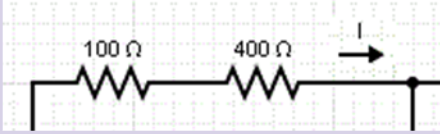
The resistors R1, R2 …., Rm in the circuit below are said to be in series because the same current passes through them:
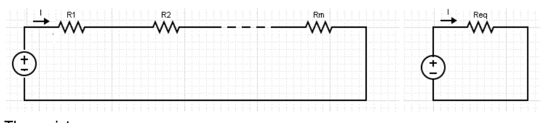
The resistors behave in the same way as the circuit on the right of resistance, where the equivalent resistance can be found by adding the individual resistance.

Since the total resistance is Req. When we use Ohm’s law to find current the equation becomes:
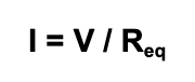
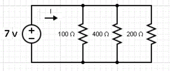
Let’s look at an example. Say we want to find the current, I, passing through, and the voltage across, each of the resistors in this circuit:
The three resistors in series have a resistance Req given by the sum of the three resistances.
Therefore, Req = 100 + 400 + 200 = 700 Ω. The current I passing through R1, R2 and R3 is the same, so we can apply Ohm’s Law I = 7 V / 700 Ω = 0.01 A
The voltage across each resistance is calculated using Ohm’s law for each resistor:
The voltage across 100Ω: VR1 = 100 × I = 100 × 0.01 = 1 V
The voltage across 400Ω: VR2 = 400 × I = 400 × 0.01 = 4 V
The voltage across 200Ω: VR3 = 200 × I = 200 × 0.01 = 2 V
It’s worth noting that the total voltage across each resistor adds up to the voltage supplied by the battery.
Resistors in Parallel
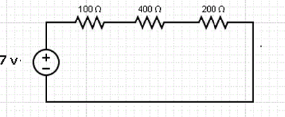
In a parallel circuit, the voltage across each of the resistors R1, R2 …., Rm in the circuit on the left is the same. They behave in the same way as the circuit on the right of resistance Req that is given by the equation:

Combinations of resistors in parallel will ALWAYS have a lower resistance then the smallest resistor present, so can be used to combine high resistors to make an equivalent low resistor:
Let’s have a look at an example. We’re going to find I in the circuit below, as well as the current passing through each of the resistors in the circuit:
The three resistors are in parallel and behave like a resistor with resistance Req given by

Multiply all terms by 400 and simplify to get
400 / Req = 4 + 1 + 2
400 / Reg = 7
Reg = 400/7
Reg = 57.14 Ω
We can now use this to work out the current in the circuit
I = V / R
I = 7 / 57.14
I = 0.1225A
We now use Ohm’s law to find the current passing through each resistor:
The current through the resistor of 100 Ω: I1 = 7 / 100 = 0.07 A
The current through the resistor of 400 Ω: I2 = 7 / 400 = 0.0175A
The current through the resistor of 200 Ω: I3 = 7 / 200 = 0.035A
A real-life example
In real life, circuits often have combinations of both series and parallel resistors. In this case, we need to calculate the equivalent resistor for each combination and may have to use the formulas more than once.
The circuit below contains a combination of series and parallel resistors, and we want to find current I:
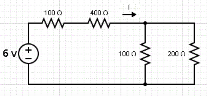
The 100Ω and the 400 Ω resistors are in series, we can combine them and call this Req1
Req1 = 100 + 400 = 500 Ω
The two resistors that are in parallel are grouped as Req2 in the equivalent circuit below and their resistance is given by the equation
1 / Req2 = 1 / 100 + 1 / 200
Req2 = 66.67Ω
So our original circuit can be replaced by
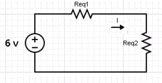
Req1 and Req2 are in series and therefore are equivalent to R given by the sum
R = Req1 + Req2 = 500 + 66.67
R = 566.67Ω
We now use Ohm’s law to find current I.
I = V / R
I= 6 / 566.67
I= 0.0106 A
Keep an eye out for our next articles looking into the principles of operation of a DC electric motor.
Interested in our courses?
You can read more about our selection of accredited online electrical engineering courses here.
Check out individual courses pages below:
Diploma in Electrical and Electronic Engineering
Higher International Certificate in Electrical and Electronic Engineering
Diploma in Electrical Technology
Diploma in Renewable Energy (Electrical)
Higher International Diploma in Electrical and Electronic EngineeringAlternatively, you can view all our online engineering courses here.
Recent Posts
Civil Engineering Courses and Diplomas: Topics, Skills and Career Routes
Civil Engineering Courses and Diplomas: Topics, Skills and Career Routes Introduction Civil engineering is the backbone of modern society. From roads and bridges to skyscrapers and water systems, civil engineers design, build, and maintain the infrastructure that keeps the world running. If you’re considering a civil engineering course or diploma, understanding what it covers is […]
What Is a Diploma in Engineering? Courses, Levels and Career Routes Explained
What Is a Diploma in Engineering? Courses, Levels and Career Routes Explained Introduction Engineering shapes the world around us, from the buildings we live in to the technology we use every day. But for many aspiring engineers, the biggest question is not whether to pursue engineering, but how to start. Traditional university degrees are not […]
Engineering Courses: How to Choose the Right Route for Your Career
Engineering Courses: How to Choose the Right Route for Your Career Introduction Choosing an engineering course can feel like standing at the beginning of several different roads, each leading towards a different kind of future. One route may lead into mechanical systems and manufacturing. Another may lead towards aircraft, infrastructure, electronics, computing, renewable energy or […]