Exploring Series, Compound, and Stepper Motors in Electrical Engineering
Introduction
Electric motors are at the heart of countless machines and devices, from household appliances to large industrial systems. Among the many types of motors used in electrical engineering, series motors, compound motors, and stepper motors hold a special place due to their unique characteristics and wide range of applications.
In this blog, we’ll break down the construction, operating principles, and practical uses of these three motor types. By the end, you’ll have a clear understanding of how each motor works, where it is best applied, and why engineers choose one over another in different scenarios.
DC series motor
A series-wound DC motor is a type of self-excited DC motor, where the field winding is connected in series with the armature winding. The field windings are exposed to the entire armature current unlike in the case of a shunt motor.
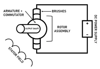
Construction of Series DC Motor
A series DC motor is constructed with the following key components and design features:
The stator is the stationary part of the motor, housing the field pole.
The field winding, also known as the series field winding, is wound on the poles. It is made of thick copper wire with a small number of turns because it carries the full armature current, requiring it to handle high current with minimal resistance.
The stator creates the magnetic field that interacts with the armature to produce torque.
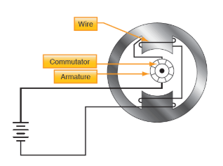
The armature is the rotating part of the motor, consisting of: Armature Core which is made of laminated steel to reduce eddy current losses and designed with slots to hold the armature winding. Armature Winding which consists of copper windings embedded in the slots of the armature core. These windings carry the current and generate the necessary electromotive force when interacting with the magnetic field. The commutator is a cylindrical structure made of segmented copper bars insulated from each other by mica. It is mounted on the shaft of the armature. It ensures the unidirectional flow of current in the armature winding, which is crucial for producing unidirectional torque. Brushes are made of carbon or graphite and rest against the commutator. They provide a sliding electrical connection between the stationary external circuit and the rotating commutator.
The series field winding is a critical part of a series DC motor and is connected in series with the armature winding. This connection means the same current flows through both the field winding and the armature, directly linking the magnetic field strength to the load current.
The frame is the outer casing of the motor, providing mechanical support and protecting the internal components. It also acts as a path for the magnetic flux generated by the field winding. The armature is mounted on the shaft, which transmits mechanical power to the load. The shaft is supported by bearings to reduce friction and ensure smooth rotation.
Construction Details
Field Windings are made with fewer turns of thicker wire to handle high current.
The number and design of poles depend on the motor’s size and application.
Both the armature and field cores are laminated to reduce core losses caused by eddy currents.
Larger motors often include ventilation ducts or fans to dissipate heat generated due to high current flow.
When voltage is applied to the motor:
The current flows through the series field winding and then through the armature winding. The series field winding generates a strong magnetic field proportional to the current. The interaction of this field with the armature current produces torque, causing the motor to rotate.
This simple but robust construction allows the series DC motor to produce high starting torque, making it ideal for applications like electric trains, cranes, and elevators.
Voltage and Current Equation of Series DC Motor
The electrical layout of a typical series-wound DC motor is shown in the diagram below.
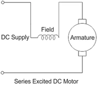
Supply voltage and current given to the electrical port of the motor are given by E and Itotal .
Since the entire supply current flows through both the armature and field conductor.
Itotal = Ise = Ia
Where, Ise is the series current(A) in the field coil and Ia is the armature current.(A)
Voltage equation of the DC motor
E = Eb + IseRse + IaRa
Where, Eb is the back emf (V), Rse is the series coil resistance(Ω) and Ra is the armature resistance.(Ω)
Since Ise = Ia, we can write
E = Eb + Ia( Ra + Rse)
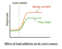
Another interesting fact about the DC series motor worth noting is that, the field flux like in the case of any other DC motor is proportional to field current
Ise ∝ Φ so Φ∝ Ise ∝Ia
The field flux is proportional to the entire armature current or the total supply current. And for this reason, the flux produced in this motor is strong enough to produce sufficient torque, even with the bare minimum number of turns it has in the field coil.
Speed and Torque of Series DC Motor
Torque-Current Relationship
In a series-wound motor, the field winding is directly connected in series with the armature winding. This means that the field current is the same as the armature current. The torque produced (T) is proportional to the product of the field flux (Φ) and the armature current (Ia)
T ∝ Φ. Ia
Since the flux (Φ) in a series motor is also directly proportional to the current (Ia) in the winding, the torque becomes proportional to the square of the current at lower loads, making it highly sensitive to current changes:
T∝ Ia2
This results in very high torque at the start, which is crucial for overcoming inertia in applications involving heavy mechanical loads.
High Starting Torque: The combination of a heavy gauge winding to handle high currents, a large magnetic field due to the high current, and the direct relationship between torque and current ensures that the motor can produce the immense torque required to start heavy loads.
Due to their ability to produce high starting torque, series-wound motors are commonly used in: Crane Hoists to lift heavy objects by overcoming initial rest inertia. Locomotives to pull train cars from a stationary position. Elevators as high torque is needed during the initial lift. Automotive Starter Motors to start engines by quickly overcoming compression resistance.
Short-Duration Operation
The high currents that flow through the series windings generate significant heat due to (I2R ) losses. Prolonged operation at such currents can lead to overheating and eventual damage to the motor components, especially the field coils. Field Coil Burnout: Since the series winding carries the full armature current, its design must prioritise handling high loads over extended periods. However, to maintain practicality and cost-efficiency, the motor is often operated for only a few seconds during high-torque startup scenarios.
At low loads, the speed of a series-wound motor can increase significantly because the load current (and hence field current) decreases. This reduces the magnetic field strength, causing the motor to run faster to maintain back EMF, which can lead to dangerously high speeds (runaway conditions) if the load is removed entirely. For this reason, series motors should never be operated without a load, as it can lead to mechanical failure or damage to the motor.
Design Considerations: Robust Field Windings: To handle high current, the series winding is made of thick copper wire with low resistance. Heat Management: Ventilation systems or thermal cut outs are often included in large motors to mitigate overheating risks during operation.
Visible Difference from a Series Motor: In a series motor, the field winding carries the entire supply current, so it is designed with thicker, low-resistance wire to handle higher currents. In contrast, the field winding of a shunt motor has a smaller diameter and higher resistance, making it distinguishable even in a static condition.
DC compound motor
A compound wound DC motor is a type of self-excited DC motor that combines the characteristics of both shunt-wound and series-wound DC motors. It features two separate field windings; this hybrid construction provides a balance of the advantages of the two types of motors, making it versatile for various applications.
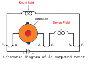
Dual Field Windings: Shunt Winding is connected parallel to the armature, this winding creates a constant magnetic field regardless of the load current. Series Winding is connected in series with the armature, this winding produces a magnetic field that varies with the load current.
Hybrid Behaviour: At light loads, the shunt winding dominates, offering good speed regulation. At heavy loads, the series winding contributes, providing high starting torque.
Compensation for Load Changes: By combining the strengths of series and shunt motors, compound motors maintain a relatively constant speed under varying loads while being capable of generating high torque during startup.
Types of Compound Wound DC Motors
Compound motors are categorised based on the polarity and connection of their windings:
Cumulatively Compounded Motor: The magnetic fields of the shunt and series windings aid each other providing high starting torque and good speed regulation. Commonly used in heavy machinery, elevators, and presses.
Differentially Compounded Motor: The magnetic fields of the shunt and series windings oppose each other, this offers poor torque at low speeds but excellent speed regulation under constant load. Rarely used due to instability at heavy loads.
Characteristics of Compound Wound DC Motor: High starting torque due to the series winding, making it suitable for applications requiring initial heavy loads. Better speed regulation than a series motor, but not as precise as a shunt motor. This balance makes it ideal for medium-load applications. Can handle sudden load variations effectively without significant changes in speed.
Applications: Compound wound DC motors are widely used in applications where high starting torque is required and speed regulation is moderately important. Examples include: Rolling mills, Printing presses, Elevators and hoists, Cranes and conveyors, Steel plants.
Advantages: They combine the best features of shunt and series motors, and can handle varying loads without excessive speed fluctuations. Provides high starting torque and stable performance.
Disadvantages: More complex construction compared to simple shunt or series motors. Higher cost due to the dual field windings.
The compound wound DC motor can further be subdivided into 2 major types on the basis of its field winding connection with respect to the armature windings, and they are:
Long Shunt Compound Wound DC Motor
A long shunt compound DC motor is a type of compound wound DC motor where the shunt field winding is connected in parallel with both the armature and the series field winding. This configuration is known as “long shunt” because the shunt winding spans (or “shunts”) the armature and series winding together.
Armature: the rotating part of the motor, consisting of a laminated core and armature windings. The armature interacts with the magnetic field to produce torque.
Series Field Winding: Wound with a few turns of thick wire to handle the full load current. It is connected in series with the armature. The magnetic field it generates varies directly with the load current.
Shunt Field Winding: Wound with many turns of thin wire, it has a high resistance. It is connected in parallel with the combination of the armature and series winding. It generates a constant magnetic field irrespective of load variations.
Commutator: mechanical rectifier that ensures unidirectional current in the armature winding.
Brushes: Provide electrical contact between the stationary and rotating parts of the motor.
Frame and Poles: The outer casing houses the windings and provides structural support. The poles provide the magnetic flux.
When a voltage is applied, current flows through the series field winding and armature. Simultaneously, a smaller current flows through the shunt field winding. The magnetic fields generated by both the series and shunt windings interact with the armature current, producing torque.The series winding contributes to high starting torque, while the shunt winding ensures speed regulation.
High starting torque due to the series winding which increases with load, making it suitable for applications requiring heavy lifting or pulling.
Speed remains relatively constant under varying loads, thanks to the shunt winding and better speed regulation than a series motor but slightly inferior to a pure shunt motor.
At high loads, the series winding dominates, providing additional torque while at light loads, the shunt winding maintains speed stability.
Applications: Long shunt compound motors are used in applications requiring: High starting torque with moderate speed regulation and smooth operation over a range of loads, such as Rolling mills, Conveyors, Elevators, Heavy-duty presses, Cranes and hoists
Advantages: Combines the benefits of series and shunt motors, Provides high starting torque and stable speed under load, Handles varying load conditions effectively.
Disadvantages: Slightly more complex design than short shunt compound motors, Higher cost due to dual field windings.
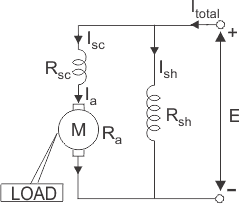
Voltage and Current Equation of Long Shunt Compound Wound DC Motor
Let E and Itotal be the total supply voltage and current supplied to the input terminals of the motor. And Ia, Ise , Ish are the values of current flowing through armature resistance Ra, series winding resistance Rse and shunt winding resistance Rsh respectively.
The current equation of a compound wound DC motor is given by
Itotal = I se + Ish
And its voltage equation is,
E = Eb + Ia(Ra + Rse)
Short Shunt Compound Wound DC Motor
A Short Shunt Compound Wound DC Motor is a type of direct current (DC) motor where the shunt field winding is connected in parallel only with the armature winding, not with the series field winding. This design provides a combination of features from both series and shunt DC motors, making it versatile for various applications.
Armature Winding: The primary winding where the working electromotive force (EMF) is induced.
Series Field Winding: A winding connected in series with the armature. It carries the full armature current and produces a strong magnetic field.
Shunt Field Winding: A high-resistance winding connected in parallel with the armature. It carries a small current and maintains a constant magnetic field.
The motor exhibits a high starting torque due to the contribution of the series field winding. It provides better speed regulation than a series motor but not as good as a pure shunt motor. The short shunt motor can operate with characteristics of both series and shunt motors, depending on the load. When the motor is energised, the armature current flows through the armature winding and the series field winding. The shunt field winding, being parallel to the armature, draws a small amount of current, creating a steady magnetic field. The interaction between the magnetic fields generated by the armature and the field windings produces torque, which causes the rotor to turn.
Applications: Short shunt compound wound DC motors are commonly used in applications requiring high starting torque, moderate speed regulation and load conditions that vary widely, typical uses include: Cranes and hoists, Elevators, Rolling mills, Heavy-duty machines
Advantages: Combines the high torque of series motors and the speed stability of shunt motors.
More efficient than series motors for variable load conditions.
Disadvantages: More complex design than simple series or shunt motors. Higher cost due to additional winding.
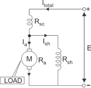
Voltage and Current Equation of Short Shunt Compound Wound DC Motor
Let, E and Itotal be the total supply voltage(V) and current (A) supplied to the input terminals of the motor. And Ia, Ise, Ish be the values of current (A) flowing through armature resistance Ra, series winding resistance Rse and shunt winding resistance Rsh (Ω) respectively.
But from the diagram above we can see
Itotal = Ise
Since the entire supply current flows through the series field winding, like in the case of a DC shunt motor
Itotal = Ia + Ish
If we combine the above equations and apply Kirchoff’s law we get
E = Eb + IaRa + IseRse
Thus the final voltage equation can be written as,
E = Eb + IaRa + Itotal Rse
Apart from the above mentioned classification, a compound wound DC motor can further be subdivided into 2 types depending upon excitation or the nature of compounding.
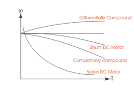
Cumulative Compounding of DC Motor
A compound wound DC motor is said to be cumulatively compounded when the shunt field flux produced by the shunt winding assists or enhances the effect of main field flux, produced by the series winding.
Φ total = Φ series + Φ shunt
Differential Compounding of DC Motor
Similarly a compound wound DC motor is said to be differentially compounded when the flux due to the shunt field winding diminishes the effect of the main series winding. This particular trait is not really desirable, and hence does not find much of a practical application.
Φ total = Φ series – Φ shunt
The net flux produced in this case is lesser than the original flux and hence does not find much of a practical application.
The compounding characteristic of the self excited DC motor is shown
Stepper motor
A stepper motor is a type of electric motor specifically designed for precise control of angular position, speed, and acceleration. Its key characteristic is that its shaft rotates in discrete steps, each corresponding to a fixed number of degrees, rather than rotating continuously like a conventional motor.
This stepping motion is achieved through the unique internal structure of the motor, which typically involves multiple electromagnets arranged in a circular pattern around a rotor. By sequentially energising these electromagnets in a controlled manner, the rotor aligns itself to specific positions, producing incremental movements.
The main advantage of stepper motors is their ability to provide accurate position control without requiring external sensors. By counting the steps performed, the exact angular position of the shaft can be determined. This eliminates the need for feedback systems such as encoders, simplifying design and reducing costs.
These features make stepper motors suitable for a wide range of applications, including:
3D printers: For precise positioning of the print head and build platform.
CNC machines: For controlling the cutting tools or material placement.
Robotics: For joint actuation and motion control.
Camera platforms: For smooth and accurate panning, tilting, or zooming.
Industrial automation: For conveyor belts, pick-and-place machines, and other systems requiring high precision.
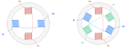
Stepper motors are available in various configurations, such as unipolar, bipolar, and hybrid designs, each with specific advantages tailored to different requirements.
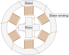
The working principle of a stepper motor is based on the interaction between its stator (stationary part) and rotor (rotating part), using electromagnetism to achieve precise movement. The motor converts electrical pulses into discrete mechanical movements, with each pulse causing the rotor to move a specific angle, known as the step angle.
Stator: Composed of electromagnets (coils) arranged in a circular pattern. Energising these coils creates magnetic poles.
Rotor: Can be made of permanent magnets (permanent magnet motors) or soft iron (variable reluctance motors). It aligns itself with the stator’s magnetic field when coils are energised.
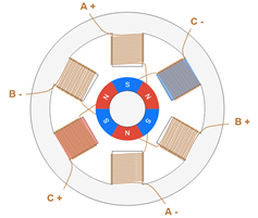
Stepping Mechanism
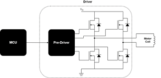
The rotor moves incrementally due to the sequential energization of stator coils. A stepper motor is controlled by applying electrical pulses to its coils in a specific sequence. This sequence creates a rotating magnetic field in the stator. The rotor aligns itself with the magnetic field, and as the field rotates (by changing which coil is energised), the rotor follows, moving in steps. The step angle is determined by the number of poles on the stator and rotor.
Formula for step angle:
Step Angle = 360º / Number of Steps per Revolution
For example, if a stepper motor has 200 steps per revolution, the step angle is 1.8º.
Control Methods
Wave Drive (One Phase On): Energises one coil at a time, providing minimal torque but simpler control.
Full Step (Two Phases On): Energises two adjacent coils simultaneously, increasing torque.
Half Step: Alternates between one-phase and two-phase energization, effectively doubling the resolution.
Microstepping: Gradually varies the current between coils to achieve finer steps and smoother motion.
Types of Stepper Motors
Permanent Magnet Stepper Motor: Uses a rotor with permanent magnets. It provides high torque at low speeds.
Variable Reluctance Stepper Motor: Has a rotor made of soft iron. It is simpler and cheaper but offers lower torque.
Hybrid Stepper Motor: Combines features of PM and VR motors for high performance and precision
Advantages: Exact positions can be controlled with out feedback sensors, they can return to a position accurately by counting steps, there is no need for complex feedback systems. Ideal for applications requiring strong, slow movements.
Interested in our Electrical Engineering Courses?
At iLearn Engineering®, we offer a diverse range of online accredited electrical engineering courses and qualifications to cater to different academic and career goals. Our courses are available in varying credit values and levels, ranging from 40 credit Engineering Diplomas to a 360 credit International Graduate Diploma.
Short Courses (40 Credits)
A selection of our more popular 40 credit electrical diplomas…
Diploma in Electrical and Electronic Engineering
Diploma in Electrical Technology
Diploma in Renewable Energy (Electrical)
First Year of Undergraduate (Level 4 – 120 Credits)
Higher International Certificate in Electrical and Electronic Engineering
First Two Years of Undergraduate (Level 5 – 240 Credits)
Higher International Diploma in Electrical and Electronic Engineering.
Degree equivalent Graduate Diploma (Level 6 – 360 Credits)
International Graduate Diploma in Electrical and Electronic Engineering
All Electrical and Electronic Courses
You can read more about our selection of accredited online Electrical and Electronic Engineering courses here.
Complete Engineering Course Catalogue (all courses)
Alternatively, you can view all our online engineering courses here.
Recent Posts
Understanding Key Performance Indicators in Manufacturing
Understanding Key Performance Indicators in Manufacturing Introduction Key Performance Indicators (KPIs), or sometimes written as Key Performance Measures, are some of the key ‘metrics’ that are used to measure the performance of an industrial system. A good KPI for a manufacturing system should be SMART, that is: Specific – It should measure a specific output […]
How Aircraft Structures Evolved: From Fragile Flyers to Engineering Masterpieces
How Aircraft Structures Evolved: From Fragile Flyers to Engineering Masterpieces Introduction As with all other aspects involved with an aircraft, the structural design and layout has changed markedly over the history of flight, in line with technological advances and new discoveries. This section will highlight some of the more substantial developments made during the history […]
Why Lean Manufacturing Matters: Principles of waste
Why Lean Manufacturing Matters: Principles of waste Introduction Lean manufacturing isn’t just a toolkit for improving efficiency, it’s a mindset that reshapes how organisations think about value. At its core, lean focuses on delivering exactly what the customer needs, when they need it, with as little waste as possible. In an increasingly competitive and resource-conscious […]