Inside the DC Shunt Motor: Design, Operation, and Performance
Summary
DC shunt motors remain a foundational technology in electric machines, prized for their reliable speed regulation and versatility in many control applications. In this post, we’ll explore the inner workings, design features, and performance characteristics of DC shunt motors, covering:
- The structural components — armature, field windings, commutator, brushes, yoke
- How the shunt winding enables stable, nearly constant speed control
- Analysis of torque, efficiency, and performance under varying load conditions
- Design trade-offs and practical applications where DC shunt motors shine
Whether you’re studying electromechanical systems or designing motor-driven solutions, you’ll gain clear insight into how DC shunt motors are built, operate, and deliver controlled performance.
Introduction
A DC motor (Direct Current motor) is an electrical machine that converts direct current electrical energy into mechanical energy. It is one of the most fundamental components in the field of electromechanical systems, playing a critical role in industrial and everyday applications due to its simplicity, reliability, and ease of control.
They are ideal for applications requiring precise speed control (e.g., conveyors, machine tools, elevators), or high starting torque (e.g., cranes, electric vehicles).
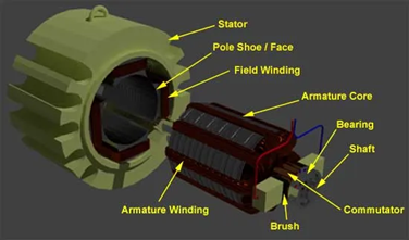
Basic Construction of a DC Motor:
The armature is a current-carrying conductor connected to the power supply via commutator segments and brushes. The armature is positioned in the magnetic field generated by either a permanent magnet or an electromagnet (north and south poles). The Commutator is a segmented device that ensures unidirectional torque by reversing the current direction in the armature windings as the motor rotates. The Brushes are Carbon or metal contacts that maintain electrical connection with the rotating commutator. The armature is placed between the poles of a magnet, producing the field required for motor operation
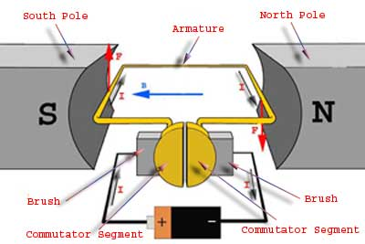
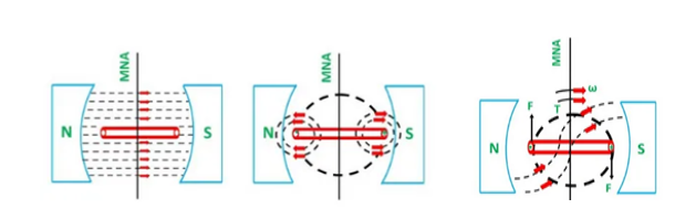
When direct current is supplied to the armature, it produces a magnetic field around the conductor. The interaction between the armature’s magnetic field and the static field (from the magnet) generates a mechanical force.
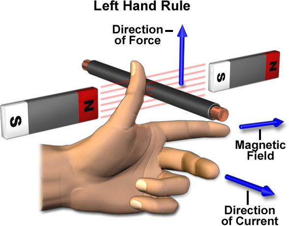
The direction of the force (and consequently the motion) is determined using Fleming’s Left-Hand Rule:
Stretch your thumb, forefinger, and middle finger perpendicular to each other.
Middle finger: Current direction (from positive to negative).
Forefinger: Magnetic field direction.
Thumb: Direction of force (motion of the conductor).
The commutator reverses the direction of the current in the armature windings at every half rotation, maintaining consistent torque and ensuring continuous rotation.
Key Points to Note: The force acting on the armature conductor is always perpendicular to both the magnetic field and the current direction, enabling rotational motion. The magnitude of the force depends on the strength of the magnetic field, the amount of current flowing through the armature and the length of the armature conductor in the magnetic field.
DC Shunt Motor
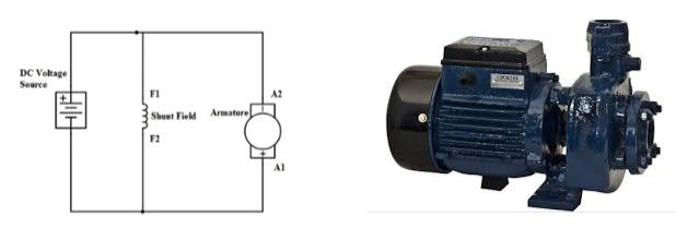
A DC shunt motor is a type of self-excited DC motor where the field windings are connected in parallel (shunted) to the armature winding. This parallel connection ensures that the field winding and the armature winding receive the same supply voltage, but the currents through each are separate.
DC Shunt Motor Equations
In a shunt wound DC motor, the current supplied from the electrical terminal (Itotal ) is split into two branches due to the parallel connection of the field winding and the armature winding. Here’s a detailed analysis of the voltage and current distribution:
Total Current (Itotal): The total current drawn from the supply is:
Itotal = Ia + Ish
Where: Ia is the current flowing through the armature winding. (A), Ish is the current flowing through the field (shunt) winding.(A)
Voltage Across Windings: Since the armature winding and field winding are connected in parallel, the voltage across both windings remains the same:
V = E + Ia Ra
Where: V id the supply voltage.(V), E is the back emf generated in the motor.(V), Ra is the armature resistance.(Ω)
Field Current ( Ish) :The field current depends on the field winding resistance (Rsh) and the supply voltage ( V )
Ish = V / Rsh
Armature Current ( Ia) :The armature current is given by:
Ia = I total – Ish
Armature Resistance Voltage Drop (Ia Ra) A small portion of the supply voltage is dropped across the armature resistance due to Ia Ra with the remaining voltage utilised to counter the back emf ( E ).
Back EMF ( E ): The back emf is generated due to the rotation of the motor and opposes the applied voltage. It is proportional to the speed ( N ) and the flux ( Φ )
E ∝ N.Φ
Power Distribution (P): The input power to the motor is:
Pinput = V. Itotal
This power is distributed as:
Power consumed by the armature winding: Ia2 Ra
Power consumed by the field winding: Ish2 Rsh
Mechanical power output: ∝ E. Ia
All forms of power are measured in Watts.(W)
These relationships are critical for analysing and troubleshooting shunt wound DC motors in practical applications.
Construction of a Shunt Wound DC Motor
The construction of a DC shunt motor is quite similar to other types of DC motors, but it has specific design features that make it unique, particularly in how it achieves torque generation and flux linkage.
Field Winding (Shunt Winding): The following design choices ensure efficient magnetic field generation without drawing excessive current.
Higher Number of Turns: The field winding has many turns of fine wire to maximise the flux linkage. Increased turns generate a strong magnetic field with a relatively small current ( Ish).
Smaller Conductor Diameter: The use of thinner wire increases the resistance ( Rsh), which limits the current flowing through the field winding.
Armature Winding: Lower Resistance, Higher Current Capacity: The armature winding is designed with thicker conductors to allow a higher current ( Ia ) to flow through it. The armature winding is exposed to the majority of the motor’s current supply.
Torque and Flux Relationship: The total torque produced is proportional to the product of the armature current (Ia) and the flux linkage (Φ)measured in Wb
T ∝ Ia.Φ
Flux (Φ): Directly related to the current flowing in the field winding (Ish) and the number of turns in the winding.
By distinguishing the field winding design, with many turns of fine wire and higher resistance, the DC shunt motor achieves steady speed characteristics and efficient performance, making it well-suited for applications requiring constant speed under varying loads.
Self-Speed Regulation of a Shunt Wound DC Motor
One of the defining characteristics of a shunt wound DC motor is the self-speed regulation. This means that the motor inherently maintains a nearly constant speed, even when the load on the motor shaft changes.
Speed Regulation: The speed of a DC motor is governed by the relationship:
N∝ Eb / Φ
Where: N is the speed of the motor.(rpm), Eb is the back EMF (∝ V – Ia Ra).(V), Φ is the magnetic flux produced by the field winding.(Wb)
The field current ( Ish) is nearly constant because the field winding resistance (Rsh) is high and the supply voltage ( V ) remains constant. Therefore, the flux (Φ) also remains constant under normal operating conditions.
How Self-Speed Regulation Works
No-Load Condition: When no load is applied to the motor, the armature current ( Ia) is very small, as it only needs to overcome the motor’s internal losses (friction and windage). The back EMF (Eb) is nearly equal to the supply voltage ( V ).
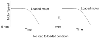
Loaded Condition: When a load is applied to the motor shaft, the motor requires more torque to drive the load. Torque ( T) is directly proportional to the armature current ( Ia), so ( Ia) increases to meet the torque demand.
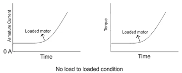
This increase in (Ia) causes a larger voltage drop across the armature resistance (Ia Ra), slightly reducing the back EMF ( Eb). A decrease in (Eb) causes a slight reduction in speed, but this is minimal due to the relatively small ( Ia Ra) drop.
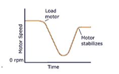
The slight reduction in speed reduces ( Eb), allowing more current to flow through the armature, generating the additional torque required to handle the load. Once the required torque is reached, the motor stabilises at a new operating point with only a small speed drop. Since the field current ( Ish) is constant, the flux (Φ) remains constant.
Minor Speed Reduction: The speed reduction needed to regulate the armature current is small because the armature resistance ( Ra) is low. This inherent feedback mechanism allows the motor to regulate its speed without external control.
Advantages of Self-Speed Regulation: Stable Performance so the motor can handle varying loads without requiring external speed controllers. Constant Speed which is ideal for applications where consistent speed is critical, such as fans, pumps, and conveyors. High efficiency reduces the need for complex control mechanisms, simplifying operation and maintenance.
Applications of Self-Speed Regulating Shunt Motors: Industrial Machinery: Lathes, drills, and milling machines. Conveyors: Systems where speed stability is essential. Pumps and Fans: Maintaining consistent flow rates or air pressure.
Interested in our Electrical Engineering Courses?
At iLearn Engineering®, we offer a diverse range of online accredited electrical engineering courses and qualifications to cater to different academic and career goals. Our courses are available in varying credit values and levels, ranging from 40 credit Engineering Diplomas to a 360 credit International Graduate Diploma.
Short Courses (40 Credits)
A selection of our more popular 40 credit electrical diplomas…
Diploma in Electrical and Electronic Engineering
Diploma in Electrical Technology
Diploma in Renewable Energy (Electrical)
First Year of Undergraduate (Level 4 – 120 Credits)
Higher International Certificate in Electrical and Electronic Engineering
First Two Years of Undergraduate (Level 5 – 240 Credits)
Higher International Diploma in Electrical and Electronic Engineering.
Degree equivalent Graduate Diploma (Level 6 – 360 Credits)
International Graduate Diploma in Electrical and Electronic Engineering
All Electrical and Electronic Courses
You can read more about our selection of accredited online Electrical and Electronic Engineering courses here.
Complete Engineering Course Catalogue (all courses)
Alternatively, you can view all our online engineering courses here.
Recent Posts
Understanding Key Performance Indicators in Manufacturing
Understanding Key Performance Indicators in Manufacturing Introduction Key Performance Indicators (KPIs), or sometimes written as Key Performance Measures, are some of the key ‘metrics’ that are used to measure the performance of an industrial system. A good KPI for a manufacturing system should be SMART, that is: Specific – It should measure a specific output […]
How Aircraft Structures Evolved: From Fragile Flyers to Engineering Masterpieces
How Aircraft Structures Evolved: From Fragile Flyers to Engineering Masterpieces Introduction As with all other aspects involved with an aircraft, the structural design and layout has changed markedly over the history of flight, in line with technological advances and new discoveries. This section will highlight some of the more substantial developments made during the history […]
Why Lean Manufacturing Matters: Principles of waste
Why Lean Manufacturing Matters: Principles of waste Introduction Lean manufacturing isn’t just a toolkit for improving efficiency, it’s a mindset that reshapes how organisations think about value. At its core, lean focuses on delivering exactly what the customer needs, when they need it, with as little waste as possible. In an increasingly competitive and resource-conscious […]