

How can we calculate the axial load-carrying capacity of a reinforced concrete column and classify it?
Following on from our previous article on the axial load-carrying capacity of a steel column, we’re going to look at the axial load-carrying capacity of a concrete column and also see how we can classify it.
What is a concrete column?
Reinforced concrete columns are large, normally rectangular, or circular in shape, and not susceptible to buckling. Due to production technology, the possibility of imperfections in reinforced concrete columns is greater than in steel columns. This means the most common failure is due to a combination of axial force and bending moment due to the action of transverse forces.
The design of reinforced concrete columns differs depending on whether it is a short or slender (long) column. So, to design a reinforced concrete column, it is first necessary to determine its slenderness.
What is column slenderness?
Column slenderness is defined as:
λ=Leimin
Where are:
- Le is the effective length of the column.
- imin: minimum radius of gyration; imin=IA,
- I: moment of inertia,
- A is the cross-section area.
The effective length of the column is calculated according to the following expression:
Le=K x L
Where are:
- K is the effective length coefficient, depending on the support conditions,
- L is the length of the column.
Where ψA and ψB are defined as follows:
A=EIa2l1+EIabl2EIa4L1+EIa5L2
B=EIb9l3+EIabl2EIb6L1+EIb7L2
Ψ=0: infinitely rigid connection. In reality, ψ=0.1 for rigid connections. Ψ = ∞ for hinged connections.
Frame supports are considered immovable if their flexibility is low, which applies to:
- horizontally supported supports,
- horizontally unsupported supports, where the influence of node displacement is negligible (the difference between the shear forces according to the 1st and 2nd order theories is less than 10%).
Proof of load-bearing capacity
Proof of load-bearing capacity in a deformed configuration (according to the theory of the 2nd order) does not have to be carried out if the additional bending moments from the axial force are negligible. This is met if one of the conditions below is met:
crit≤25
crit16Ed
Where are:
Ed=NEdAc·fcd
For columns of immovable systems that are not loaded with shear loads between the nodes, it is valid:
crit≤25·2-e01e02 , for e01e02.
Let’s look at an example. Take a 2m-long column with one end that has ψ1 = 1.0 and the other ψ2 = 0.1. It has a cross-section dimension of 40/40cm. The system is immovable, and we’re going to calculate the column slenderness λ.
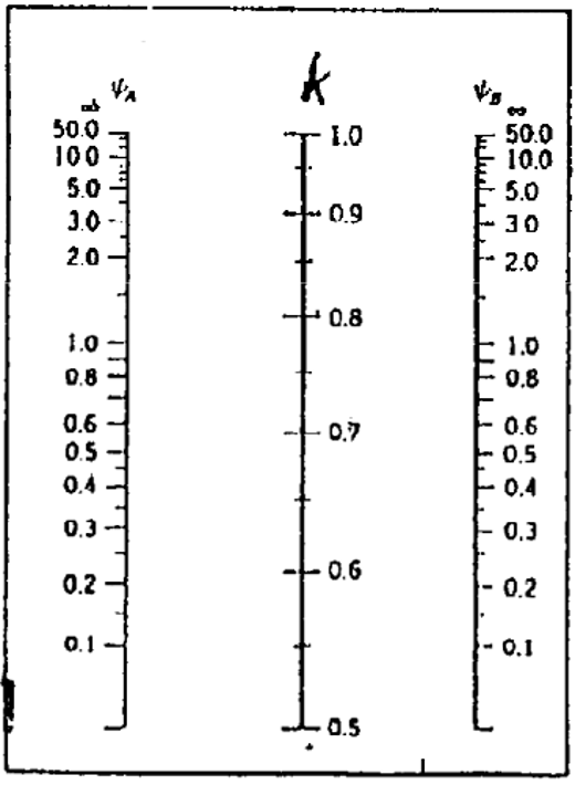
K = 0.65
Le=K x L = 0.65 x 2.0 m = 1.3 m.
A = 0.4 x 0.4 = 0.16 m2
I=b x h312 = 0.4 x 0.4312 = 0.002133 m4
imin=IA=0.0021330.16=0.1155 m
λ=Leimin=1.3m0.1155m=11.25
In our next articles, we’re going to dive into the vibration of various structures and how they are affected, so make sure you check them out.
Interested in our courses?
Interested in civil or mechanical engineering? Find out more about all the civil engineering courses we have available by clicking here, and the mechanical engineering courses by clicking here.
Diploma in Mechanical Engineering
Diploma in Mechanical Technology
Diploma in Sustainable Construction
Diploma in Structural Engineering
Diploma in Building and Construction Engineering
Higher International Certificate in Civil Engineering
Higher International Diploma in Civil Engineering
Higher International Diploma in Mechanical Engineering
Higher International Certificate in Mechanical Engineering
Alternatively, you can view all our online engineering courses here.
Recent Posts
Types of Aircraft Drag Explained: Induced, Profile and Interference Drag
Types of Aircraft Drag Explained: Induced, Profile and Interference Drag An aircraft experiences several forms of aerodynamic drag at the same time. Some result from generating lift, some arise as air flows over the aircraft’s surfaces, and others are created when airflow around neighbouring components interacts. For a conventional aircraft in subsonic flight, total drag […]
Induced Drag Explained: Why Flying Slower Can Increase Drag
Induced Drag Explained: Why Flying Slower Can Increase Drag Why can an aircraft experience more drag when it flies more slowly? We usually associate greater speed with greater air resistance, but a wing must also generate enough lift to support the aircraft. Induced drag is the drag associated with producing lift on a finite-span wing. […]
Laminar vs Turbulent Boundary Layers: Why Airflow Separates from Aircraft Wings
Laminar vs Turbulent Boundary Layers: Why Airflow Separates from Aircraft Wings Airflow around an aircraft wing is often shown as smooth streamlines passing neatly over the aerofoil. In reality, the thin layer of air immediately next to the wing surface behaves very differently from the undisturbed airflow further away. This region is called the boundary […]