From Flux to EMF: Demystifying Mutual Inductance
Introduction
Magnetic flux and electromotive force might seem like abstract physics concepts — but they’re the key to understanding how coils interact, transformers work, and energy gets transferred across air gaps. In this post, we’ll take you on a clear, intuitive journey:
- Starting from magnetic flux fundamentals
- Showing how flux in one coil induces voltage in a neighboring coil
- Defining and explaining mutual inductance
- Demonstrating how this concept forms the backbone of transformers, inductors, and many electromagnetic systems
Whether you’re learning mutual inductance for the first time or brushing up on your electromagnetic theory, by the end you’ll have a clear grasp of how flux becomes EMF in coupled coils.
Mutual Inductance is the phenomenon where the magnetic field generated by current in one coil induces an EMF (voltage) in an adjacent coil. This is different from self-induction, where the changing magnetic field around a coil induces EMF within the same coil.
When two or more coils are magnetically linked by a common magnetic flux, they exhibit mutual inductance. The changing current in one coil induces EMF in the adjacent coil. This is the fundamental operating principle of transformers, motors, and generators.
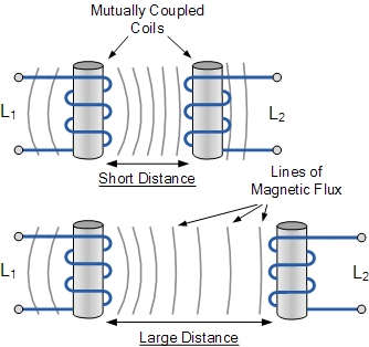
Positioning Dependence: The amount of mutual inductance is heavily influenced by the relative positioning of the two coils: Close positioning and alignment maximise magnetic flux linkage, resulting in a high mutual inductance. Greater distance or different angles reduce flux linkage, decreasing the induced EMF and mutual inductance.
Interference: Mutual inductance can sometimes be undesirable, as stray or leakage inductance from one coil may interfere with nearby components. This effect can often be mitigated with electrical shielding to ground potential.
Mutual Inductance between Coils
The mutual inductance between two coils can be significantly increased by:
Positioning the coils on a common soft iron core, which enhances magnetic coupling by concentrating and directing the magnetic flux.
Increasing the number of turns in either coil, as more turns mean more flux linkage and thus a greater induced EMF. When the two coils are tightly wound on top of each other over a common soft iron core, unity coupling is said to exist. In this configuration, flux leakage is minimised, allowing nearly perfect flux linkage between the coils. In such cases, the mutual inductance M can be maximised, as virtually all the magnetic flux generated by the first coil links to the second coil.
This principle of enhanced mutual inductance through close coupling and an iron core is foundational in transformers, where efficient energy transfer relies on maximising flux linkage between the primary and secondary windings.
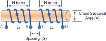
M = (μ0 x μr xN1 x N2 x A) / ℓ
Where:
µo is the permeability of free space (4.π.10-7 F/m)
µr is the relative permeability of the soft iron core (F/m)
N is in the number of coil turns
A is in the cross-sectional area in m2
ℓ is the coils length in metres
Mutual Inductance

The mutual inductance M12 between two coils, where coil one L1 has a current I1 and N1 turns, and coil two L2 has N2 turns, is the result of the magnetic field generated by the current in coil one that links with coil two.
The mutual inductance M12 ( Henry, H) of coil two with respect to coil one depends on their relative positioning and is calculated by the formula:
M12 = N2 x Φ12 / I 1
where: N2 is the number of turns in coil two, Φ12 is the magnetic flux through coil two due to the current I1 in coil one. ( Wb)
The mutual inductance depends on factors such as the distance and orientation of the coils and any shared magnetic core, which can increase flux linkage and therefore the mutual inductance value. This principle is key in transformers and other devices that rely on magnetic coupling between coils.
The mutual inductance between two coils is reciprocal, meaning that the mutual inductance of coil one with respect to coil two M21 is the same as the mutual inductance of coil two with respect to coil one M12.
Thus, we can write: M12 = M21 = M
This relationship holds regardless of the size, number of turns, relative position, or orientation of the two coils. Mutual inductance M represents the magnetic coupling between two inductors or coils, influenced by factors such as distance and arrangement.
In contrast: Self-inductance (L) characterises an inductor as an individual component, describing the induced EMF within itself due to its own changing current.
Mutual inductance reflects the interaction between two inductors, where a changing current in one coil induces an EMF in the other coil through magnetic coupling.
L1 =( μ0 x μr x N12 x A) / ℓ and L2 = (μ0 x μr x N22 x A ) / ℓ
By cross-multiplying the two equations above, the mutual inductance, M that exists between the two coils can be expressed in terms of the self inductance of each coil.giving us a final and more common expression for the mutual inductance between the two coils of:
M2 = L1L2
Mutual Inductance Between Coils
In practice, 100% magnetic coupling between two coils (L1 and L2) is unattainable due to flux leakage and positional factors. Although perfect coupling is impossible, the magnetic coupling can approach 100% in specially designed inductive coils.
The fraction of the total magnetic flux that links both coils is represented by the coefficient of coupling, denoted by the letter k . This coefficient expresses how closely the coils are magnetically coupled and is defined as:
Thus, the mutual inductance between the two coils in real conditions is given by
M = k √(L1L2)
where:
k ranges between 0 (no coupling) and 1 (ideal or near-perfect coupling).
k close to 1 indicates strong magnetic coupling with minimal flux leakage.
L1 and L2 are the self-inductances of coils L1 and L2, respectively.(H)
When the coefficient of coupling, k is equal to 1, (unity) such that all the lines of flux of one coil cuts all of the turns of the second coil, that is the two coils are tightly coupled together, the resulting mutual inductance will be equal to the geometric mean of the two individual inductances of the coils.
Also when the inductances of the two coils are the same and equal, L1 is equal to L2, the mutual inductance that exists between the two coils will equal the value of one single coil as the square root of two equal values is the same as one single value as shown.
M = √L1L2 = L
Example
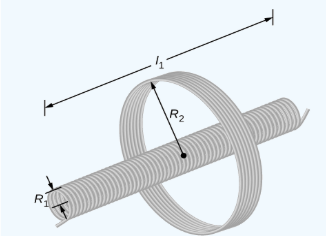
The diagram shows a coil of N2 turns and a radius of R2 surrounding a long solenoid of length l1, radius R1 and N1 turns.
a. What is the mutual inductance of the two coils?
b. If N1 = 500 turns, N2 = 10 turns, R1 = 3.10cm, l1=75cm and the current in the solenoid is changing at a rate of 200A/s. What is the emf induced in the surrounding coil?
Solution:
The magnetic flux ф21 through the surrounding coil is
ф21 = B1 x ㄫ x R12
= ( μ0 x N1 x I1 x ㄫ x R12 ) / ℓ
If we now use the equation for mutual inductance
M = (N2 x ф21 ) / I1
M = N2 / I1 x ( μ0 x N1 x I1 x ㄫ x R12) / ℓ1
M = ( μ0 x N1 x N2 x ㄫ x R12 ) / ℓ1
substituting the values into the equation gives:
M = ((4ㄫx10-7) x 500 x 10 x ㄫ x (0.0310) 2 )/ 0.750
M = 2.53×10⁻⁵H
We can then calculate the emf form the following equation:
Emf = -MdI1/ dt
Emf = -(2.53×10⁻⁵ ) 200
Emf = -5.06×10⁻³V
Example 2.
A solenoid of 500 turns is wound on an iron core of relative permeability 800. The length and radius of the solenoid are 40 cm and 3 cm respectively. Calculate the average emf induced in the solenoid if the current in it changes from 0 to 3 A in 0.4 second.
Solution
N = 500 turns; µr = 800 ; μo = 4πx10-7, l = 40 cm = 0.4 m; r = 3 cm = 0.03 m;
di = 3 – 0 = 3 A; dt = 0.4 s
Area = πr2 = 3.14 x ( 3×10⁻²)2 = 2.8×10⁻³ m2
n = N/l = 500 / 0.4 = 1250
L = μo x μr x n2 x A x l
L = 4πx10-7 x 800 x 500 x 12502 x 2.8×10-3 x 0.4
L = 1.77H
Emf = Ldi/dt
Emf = (1.77 x 3) / 0.4
Emf = 13.275V
Example 3:
Two inductors whose self-inductances are given as 75mH and 55mH respectively, are positioned next to each other on a common magnetic core so that 75% of the lines of flux from the first coil are cutting the second coil. Calculate the total mutual inductance that exists between the two coils
M = k √L1L2
M = 0.73 √75 x 55
M = 48.2mH
Example 4:
When two coils having inductances of 5H and 4H respectively were wound uniformly onto a non-magnetic core, it was found that their mutual inductance was 1.5H. Calculate the coupling coefficient that exists between.
k = M / √L1L2 = 1.5 / √5×4 = 0.335 = 33.5%
Interested in our Electrical Engineering Courses?
At iLearn Engineering®, we offer a diverse range of online accredited electrical engineering courses and qualifications to cater to different academic and career goals. Our courses are available in varying credit values and levels, ranging from 40 credit Engineering Diplomas to a 360 credit International Graduate Diploma.
Short Courses (40 Credits)
A selection of our more popular 40 credit electrical diplomas…
Diploma in Electrical and Electronic Engineering
Diploma in Electrical Technology
Diploma in Renewable Energy (Electrical)
First Year of Undergraduate (Level 4 – 120 Credits)
Higher International Certificate in Electrical and Electronic Engineering
First Two Years of Undergraduate (Level 5 – 240 Credits)
Higher International Diploma in Electrical and Electronic Engineering.
Degree equivalent Graduate Diploma (Level 6 – 360 Credits)
International Graduate Diploma in Electrical and Electronic Engineering
All Electrical and Electronic Courses
You can read more about our selection of accredited online Electrical and Electronic Engineering courses here.
Complete Engineering Course Catalogue (all courses)
Alternatively, you can view all our online engineering courses here.
Recent Posts
Understanding Key Performance Indicators in Manufacturing
Understanding Key Performance Indicators in Manufacturing Introduction Key Performance Indicators (KPIs), or sometimes written as Key Performance Measures, are some of the key ‘metrics’ that are used to measure the performance of an industrial system. A good KPI for a manufacturing system should be SMART, that is: Specific – It should measure a specific output […]
How Aircraft Structures Evolved: From Fragile Flyers to Engineering Masterpieces
How Aircraft Structures Evolved: From Fragile Flyers to Engineering Masterpieces Introduction As with all other aspects involved with an aircraft, the structural design and layout has changed markedly over the history of flight, in line with technological advances and new discoveries. This section will highlight some of the more substantial developments made during the history […]
Why Lean Manufacturing Matters: Principles of waste
Why Lean Manufacturing Matters: Principles of waste Introduction Lean manufacturing isn’t just a toolkit for improving efficiency, it’s a mindset that reshapes how organisations think about value. At its core, lean focuses on delivering exactly what the customer needs, when they need it, with as little waste as possible. In an increasingly competitive and resource-conscious […]