From Joints to Precision: The Operation of Robot Manipulators Explained
Introduction
A robot manipulator, commonly known as a robotic arm, is an electronically controlled mechanism made up of multiple connected segments or joints. It performs tasks by moving and interacting with its environment, mimicking the motion and functionality of a human arm. These manipulators are widely used in the industrial manufacturing sector due to their precision, versatility, and ability to handle repetitive tasks. They play a crucial role in tasks like assembly, welding, painting, and material handling, contributing significantly to efficiency and productivity in manufacturing.
A robotic manipulator is structured as a kinematic chain, composed of an arrangement of links and joints.
Links: These are the rigid segments that form the backbone of the manipulator, connecting each joint.
Joints: The joints connect two links and allow relative movement between them, creating what is known as a kinematic pair (a mobile connection between two links).
The combination of several kinematic pairs forms the kinematic chain of the manipulator, allowing it to move in various ways to complete tasks.
The end-effector is the device or tool attached to the end of the manipulator, allowing it to interact with objects in its environment. This could be a gripper, welding tool, or any specialised attachment suited to a particular task.
By structuring links and joints into a kinematic chain, robotic manipulators achieve flexibility and movement, making them highly effective for a range of industrial applications.
Type of Joints
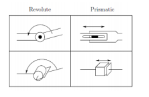
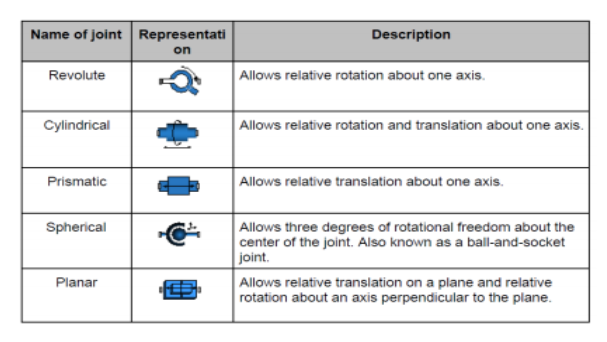
In robotic manipulators, joints are typically classified as either rotary (revolute) or linear (prismatic):
Revolute (R) Joint: This joint functions like a hinge, allowing rotational motion between two links. It enables one link to rotate relative to another around a fixed axis, providing angular movement. Revolute joints are common in applications that require pivoting or swinging motions.
Prismatic (P) Joint: This joint allows linear movement between two links, enabling one link to slide along a straight path relative to another. Prismatic joints are essential for tasks that require straight-line extension or retraction.
These two primary joint types can be combined to create more complex motion. For example, a spherical joint can be represented as a series of three revolute joints, each allowing rotation around a different axis, with zero link lengths in between. This allows spherical joints to achieve rotational freedom in multiple directions, which is valuable for complex manipulator movements requiring 3D orientation control. By combining these basic joint types, robotic manipulators achieve a wide range of movement possibilities, tailored to various industrial tasks and applications.
Manipulator Workspace and Degree of Freedom (DOF)
Degrees of Freedom define the ways a mechanical system or device, such as a robotic manipulator, can move. Each DOF represents an independent mode of motion either linear or rotational that the system can achieve. For robotic manipulators, the DOF is determined by the number of joints, with each joint contributing one DOF.
Typically, a manipulator needs at least six DOF to fully control its end-effector in 3D space:
- Three DOF for positioning (moving along the X, Y, and Z axes),
- Three DOF for orientation (pitch, yaw, and roll) to achieve any desired orientation.
With fewer than six DOF, a manipulator cannot reach every point in its workspace with any orientation, limiting its versatility. However, as the number of joints and links increases, so does the complexity of control, making highly articulated manipulators more challenging to manage.
For certain tasks, such as navigating around obstacles or reaching behind structures, manipulators may need more than six DOF to achieve flexibility and precision.
A manipulator with more than six DOF is referred to as a kinematically redundant manipulator, offering extra flexibility for complex tasks at the cost of increased control complexity.
Workspace
The workspace of a robotic manipulator refers to the total volume that the end-effector can access as the manipulator executes all possible motions. The workspace can be determined either analytically or experimentally.
The size and shape of a manipulator’s workspace are influenced by both the geometry of the manipulator and constraints on its joints. For instance, a revolute joint may not allow a full 360° rotation, limiting the reach of the end-effector.
The workspace is typically divided into two regions:
- Reachable Workspace: The entire set of points the manipulator’s end-effector can reach.
- Dexterous Workspace: A subset of the reachable workspace, consisting of points the end-effector can reach with any orientation.
The dexterous workspace is thus more restricted than the reachable workspace, as it requires that the manipulator can control both the position and the orientation of the end-effector at each point. Understanding both the reachable and dexterous workspaces is essential for designing manipulators that meet the requirements of specific tasks, ensuring that they can access the necessary areas with adequate flexibility.
Robot Manipulator Classifications
Robot manipulators are classified based on criteria such as power source, joint actuation, geometry, intended application, and control method, aiding in selecting the right robot for a specific task. For example, a hydraulic robot provides strong, powerful movements ideal for heavy-duty tasks but would not be suitable for sensitive applications like food handling or clean rooms. Robots also vary by kinematic structure (e.g., Cartesian, SCARA, or articulated), which affects their movement and workspace, and by control methods, such as teach pendants or offline programming, which impact usability and flexibility. This classification system ensures that each robot is matched to its optimal environment and application, enhancing productivity, safety, and task efficiency across various industries.
Power source classification
Robot manipulators can be classified by their power source, each offering unique advantages and limitations:
Electrically Powered: These robots are driven by DC or AC servo motors, making them popular for their low cost, cleanliness, and quiet operation. They are well-suited for environments where noise control and a clean workspace are essential, and they offer precise control, making them versatile across various applications.
Hydraulically Powered:These are ideal for applications requiring high speed, responsiveness, and torque, particularly in lifting heavy loads. However, hydraulic robots have drawbacks, including fluid leaks, higher maintenance needs, and peripheral equipment requirements. They are also relatively noisy, which limits their use in settings where quiet operation is essential.
Pneumatically Powered: These are inexpensive and simple to operate, making them accessible for basic applications. However, they lack precise control, limiting their suitability and popularity in tasks that require high accuracy. Consequently, pneumatic robots are typically used in simpler applications where exact positioning is less critical.
Each power source offers specific benefits, and the choice depends on the demands of the application, from the strength and responsiveness of hydraulic systems to the precision of electric robots and the simplicity of pneumatic systems.
Control methods classification
Robot manipulators are classified by control methods into non-servo and servo robots:
Non-Servo Robots: These are the earliest robots, using open-loop control. Without feedback, their motion is limited to predetermined stops, making them ideal for simple, repetitive tasks like materials transfer but not suitable for applications needing precision or flexibility.
Servo Robots: These robots use closed-loop control with feedback, enabling multifunctionality and reprogrammability. Servo robots are versatile and suitable for complex tasks, as they can adjust movements based on real-time feedback.
Servo-Controlled Robots are further divided based on the controller’s guidance of the end-effector:
- Point-to-Point Robots: These robots move between specific, taught points without control over the path between them. Points are typically programmed using a teach pendant and then stored for playback. Due to limited path control, point-to-point robots are restricted to applications that don’t require precision along the entire movement path.
- Continuous Path Robots: These robots can control the entire path of the end-effector, allowing for smooth, accurate motion, such as tracing a welding seam or following a precise contour. These robots often offer control over velocity and acceleration,
- making them suitable for applications requiring consistent, precise movement along a path
Overall, the control method significantly influences a robot’s functionality and suitability for different applications. Non-servo robots are ideal for simple, fixed tasks, while servo robots, especially continuous path robots, are essential for tasks that require precision, flexibility, and dynamic movement control.
Kinematic structure classification
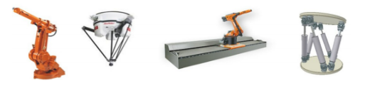
Robotic manipulators can be classified based on their kinematic structure into serial, parallel, and hybrid types:
Serial Manipulators: In a serial manipulator, links and joints are connected in a sequence to form an open kinematic chain. Each joint adds an additional degree of freedom, allowing for extensive reach and flexibility. These manipulators are commonly seen in robotic arms and are well-suited for tasks requiring wide-ranging movements, like assembly and pick-and-place
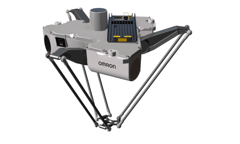
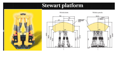
Parallel Manipulators: In parallel manipulators, links and joints form a closed kinematic chain where multiple arms support the end-effector. This structure provides higher rigidity, stability, and load-bearing capacity, often with greater precision. Parallel manipulators are used in applications like flight simulators and high-speed, high-precision positioning tasks.
Hybrid Manipulators: Hybrid manipulators combine both serial and parallel structures, taking advantage of the flexibility of serial chains and the stability of parallel chains. This combination enhances both reach and precision, making hybrid manipulators suitable for complex tasks requiring both flexibility and accuracy.
Each type of manipulator has unique strengths, with serial manipulators offering reach and flexibility, parallel manipulators providing stability and precision, and hybrid manipulators delivering a balanced combination of both for complex applications.
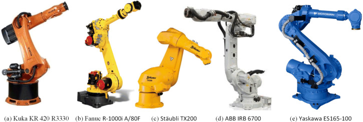
Types of Serial Manipulators
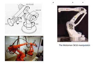
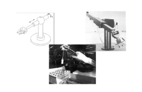
Articulated Manipulators (RRR) : An articulated manipulator is an industrial robot with a rotary joint, also known as a revolute or anthropomorphic manipulator due to its human arm-like structure. Articulated robots can vary from simple designs with two joints to complex systems with 10 or more interacting joints, providing extensive movement capability.
In a typical three-jointed articulated robot: The first joint’s axis is vertical, enabling rotation of the entire arm.The second and third joints’ axes are parallel, allowing additional flexibility and movement within the plane of the arm.
This configuration gives the articulated robot significant movement freedom within a compact space, making it ideal for tasks requiring reach and dexterity in tight or constrained environments, such as assembly, welding, and material handling.
Spherical (RRP) Manipulator : A spherical manipulator, also known as a polar manipulator, is a type of robot with two rotary (revolute) joints and one prismatic joint. This design enables the end-effector to move within a spherical coordinate system, allowing reach within a spherical or partially spherical work envelope.
In a spherical manipulator: The three axes (z₀, z₁, and z₂) are mutually perpendicular, creating a structure where the joint variables correspond to the spherical coordinates of the end-effector relative to the base.
This design once offered an effective way to achieve wide reach with a compact structure, but spherical manipulators have become less practical in industrial applications with the rise of 6-axis articulated manipulators. Modern articulated robots provide more versatility and flexibility, as they offer complete 3D positioning and orientation capabilities, which better meet the demands of contemporary industrial tasks.
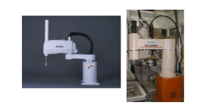
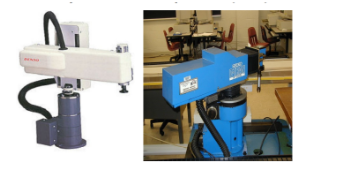
SCARA Manipulator (RRP): SCARA (Selective Compliant Articulated Robot for Assembly). This robot configuration uses two rotary (revolute) joints followed by one prismatic joint (RRP), with all three axes parallel (z₀, z₁, and z₂). The SCARA design is particularly suited for assembly operations, as its structure provides both high precision with speed and efficiency in tasks like assembly, packaging, and material handling, due to its compact, selective compliance in the horizontal plane.
Cylindrical Manipulator (RPP): A cylindrical manipulator uses an RPP joint configuration, with: The first joint is revolute (R), allowing rotation around the base. The second and third joints are prismatic (P), providing linear movement along the horizontal and vertical axes. This setup positions the end-effector based on cylindrical coordinates relative to the base, enabling a work envelope in the shape of a cylinder. The rigid structure of a cylindrical manipulator supports large payloads and ensures good repeatability, making it ideal for applications that require strength, stability, and consistent performance, such as heavy material handling and straightforward assembly operations.
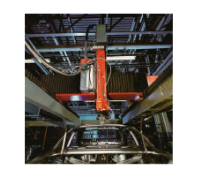
Cartesian Manipulator (PPP) A Cartesian manipulator, also known as a rectangular, rectilinear, or gantry robot, is characterised by its cuboidal workspace. This design uses three prismatic (linear) joints that allow the end-effector to move to any position within the cubic or cuboid workspace.
The joint variables correspond to Cartesian (X, Y, Z) coordinates relative to the base, allowing straightforward positioning. This configuration has the simplest kinematic structure of all manipulator types, making it easy to control and program.
Due to its stable, linear motion and precision, the Cartesian manipulator is especially useful for material transfer tasks, table-top assembly, and applications where precise, straight-line movement is essential.
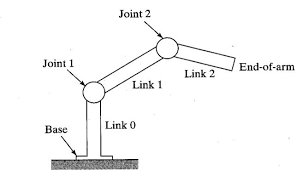
Robot Manipulator Joints
In a robot manipulator with n joints, there are (n + 1) links. Each joint connects two adjacent links, enabling motion through a sequence of articulated components.
Numbering: Joints are numbered from 1 to n, and links from 0 to n. Joint i connects links (i – 1) and i, with the location of joint i fixed with respect to link (i – 1).
Actuation and Movement: When joint i is actuated, it moves link i, while link (i – 1) remains fixed. Link 0 is permanently fixed, serving as the base of the manipulator.
Joint Variables (Joint Space): Each joint i is associated with a joint variable qi, representing its position or angle. The joint space, or joint vector, is the set of all joint variables that describe the manipulator’s configuration.
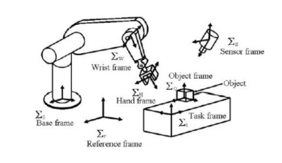
Coordinate Frames: For each link, a coordinate frame (oi, xi, yi, zi) is rigidly attached, following the right-hand rule to establish positive rotation directions around each axis. The base frame (o0, x0, y0, z0) is attached to link 0 and is referred to as the inertia (base) frame.
Right-Handed Coordinate System: The right-handed coordinate system, along with the right-hand rule, is used to define orientations and positive rotational directions in three dimensions, providing a consistent framework for describing the manipulator’s movements.
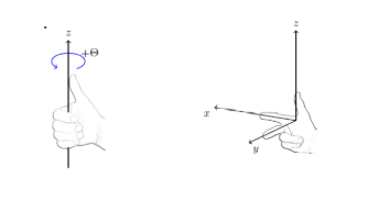
This structure allows for precise description and control of each link’s position and orientation within three-dimensional space, forming the foundation for defining and managing the manipulator’s movements in joint space.
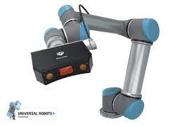
Vision Systems
Vision systems in robotics have revolutionised industrial automation by enhancing the efficiency, accuracy, and versatility of robotic applications. As manufacturing demands grow, computer-vision-based robotic guidance has become a key technology enabling robots to achieve greater performance, precision, and flexibility. Over recent years, advancements in vision technology have greatly improved the reliability, payload capacity, and application diversity of robots, replacing older encoder-based tracking with machine-vision-based feature tracking.
Vision-guided robots can perform various tasks by analysing visual data, including:
- Determining part orientation to accurately pick up objects.
- Verifying the presence and correct positioning of parts.
- Operating in either “see and move” mode (deciding movement based on pre-processed visual data) or real-time mode (processing visual input while moving).
Both 2-D and 3-D vision systems are used in robotic guidance depending on the task complexity. Real-time 3-D vision is especially valuable for guiding autonomous robots in dynamic environments, while 2-D vision suffices for simpler tasks.
Applications of Vision-Based Robotic Guidance
Vision-based robotics has unlocked a wide array of advanced applications across various industries, enhancing both efficiency and precision in automated processes.
Manufacturing: Vision-guided robots perform intricate pick-and-place tasks, especially in electronics assembly, where they position tiny components on circuit boards with high accuracy. In automotive and heavy manufacturing, robots equipped with 3-D vision systems tackle bin picking, sorting through randomly placed parts and delivering them for assembly or machining. This adaptability is invaluable in high-mix, high-volume environments where parts are constantly moving and varying in shape.
For quality inspection and sorting, vision systems empower robots to detect defects and categorise products based on attributes like size, colour, and shape. This is common in food and beverage processing, where robots quickly sort fruits or check for quality, and in pharmaceuticals, where vision-guided robots inspect pills for defects or missing labels.
Assembly line : Vision systems allow robots to track moving items on conveyors, making precise adjustments in real time to account for variations in products or packaging. For example, in multi-product assembly lines, robots handle items with different sizes and shapes, enhancing flexibility and reducing the need for reconfiguration.
Agriculture and food processing: In fields, vision-enabled robots selectively harvest ripe fruits or vegetables, while in food packaging facilities, they sort and prepare items based on size and quality. This ensures only top-quality produce makes it to packaging.
Complex assembly and path tracking(welding and machining): Vision-based robots follow exact contours and paths, essential for tasks like automotive frame welding or precise cutting. By adapting in real time, they maintain high standards in demanding applications.
Autonomous navigation in warehouses: AGVs (automated guided vehicles) equipped with cameras navigate safely around obstacles. In medical fields, vision-guided robots aid in packaging and surgical assistance, where precision is critical to ensure safety and effectiveness.
Through these applications, vision-based robotics is redefining what robots can achieve, offering unparalleled flexibility, adaptability, and quality across diverse fields.
Interested in our Electrical Engineering Courses?
At iLearn Engineering®, we offer a diverse range of online accredited engineering courses and qualifications to cater to different academic and career goals. Our courses are available in varying credit values and levels, ranging from 40 credit Engineering Diplomas to a 360 credit International Graduate Diploma.
Short Courses (40 Credits)
A selection of our more popular 40 credit electrical diplomas…
Diploma in Electrical and Electronic Engineering
Diploma in Electrical Technology
Diploma in Renewable Energy (Electrical)
First Year of Undergraduate Electrical (Level 4 – 120 Credits)
Higher International Certificate in Electrical and Electronic Engineering
First Two Years of Undergraduate Electrical (Level 5 – 240 Credits)
Higher International Diploma in Electrical and Electronic Engineering.
Degree equivalent Graduate Diploma Electrical (Level 6 – 360 Credits)
International Graduate Diploma in Electrical and Electronic Engineering
All Electrical and Electronic Courses
You can read more about our selection of accredited online Electrical and Electronic Engineering courses here.
Complete Engineering Course Catalogue (all courses including industrial, mechanical and computer engineering)
Alternatively, you can view all our online engineering courses here.
Recent Posts
Civil Engineering Courses and Diplomas: Topics, Skills and Career Routes
Civil Engineering Courses and Diplomas: Topics, Skills and Career Routes Introduction Civil engineering is the backbone of modern society. From roads and bridges to skyscrapers and water systems, civil engineers design, build, and maintain the infrastructure that keeps the world running. If you’re considering a civil engineering course or diploma, understanding what it covers is […]
What Is a Diploma in Engineering? Courses, Levels and Career Routes Explained
What Is a Diploma in Engineering? Courses, Levels and Career Routes Explained Introduction Engineering shapes the world around us, from the buildings we live in to the technology we use every day. But for many aspiring engineers, the biggest question is not whether to pursue engineering, but how to start. Traditional university degrees are not […]
Engineering Courses: How to Choose the Right Route for Your Career
Engineering Courses: How to Choose the Right Route for Your Career Introduction Choosing an engineering course can feel like standing at the beginning of several different roads, each leading towards a different kind of future. One route may lead into mechanical systems and manufacturing. Another may lead towards aircraft, infrastructure, electronics, computing, renewable energy or […]