From Power Stations to Your Home: The Role of Transformers
Introduction
Since their invention in the late 19th century, electromagnetic transformers have become a cornerstone of electrical power systems. Operating on Faraday’s law of electromagnetic induction, a transformer enables efficient energy transfer between circuits, typically to adjust voltage levels for generation, transmission, and utilization. Whether in massive utility substations or compact chargers, transformers are indispensable in shaping the reliability and scalability of modern electrical networks. This article introduces their operating principles, core construction, and applications across industry and everyday technology.
Transformer construction
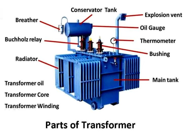
Core: The core is made of laminated iron or steel sheets to minimise energy loss due to eddy currents. It provides a path for the magnetic flux generated by the current in the primary winding. The core’s design (core-type or shell-type) influences the transformer’s efficiency and application.
Windings: The primary winding is the coil connected to the input voltage source. When an alternating current flows through it, it creates a magnetic field in the core. The secondary winding is the coil connected to the output circuit, this is where the voltage is induced due to the magnetic field in the core, transferring energy to the secondary circuit.
Insulation: Windings are insulated to prevent electrical contact between coils and the core. This insulation maintains safety and improves the transformer’s durability.
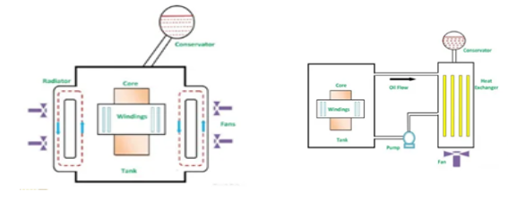
Tank and Cooling System: The windings and core are often enclosed within a tank filled with oil or other coolant. The oil helps to insulate and cool the transformer, as heat is generated during operation. For large transformers, additional cooling methods like radiators, fans, or pumps may be used to dissipate heat effectively.
This construction allows the transformer to efficiently transfer energy between circuits by converting voltage levels, with minimal energy loss and heat generation, making it crucial for electrical transmission and distribution networks.
Transformer Construction of the Core
Transformers are classified depending on how the windings are wound around the core as either core or shell type.
In both types of transformer core design, the magnetic flux linking the primary and secondary windings travels entirely within the core with no loss of magnetic flux through air.
Core type Transformer
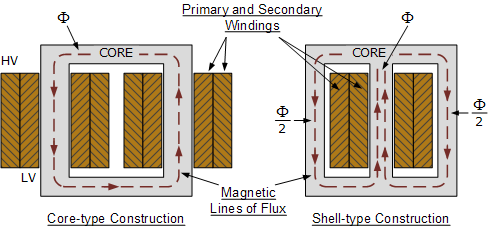
In a core-type transformer, the core has two vertical limbs and two horizontal sections called yokes, forming a rectangular shape that provides a common magnetic circuit. The High Voltage and Low Voltage cylindrical coils are placed on each limb, with the windings arranged concentrically.
Unlike having all the primary windings on one limb and all the secondary windings on the other, this design places half of each winding (primary and secondary) on each limb. This configuration enhances magnetic coupling, allowing the magnetic field to link both windings simultaneously, which improves energy transfer efficiency. However, some magnetic lines, known as “leakage flux,” flow outside the core due to this arrangement, which is an inherent characteristic of core-type transformers.
Shell Type Transformer
In a shell-type transformer, the core has a central limb with two outer limbs, forming a structure that supports a double magnetic circuit. Both the High Voltage and Low Voltage windings are placed on the central limb, which has twice the cross-sectional area of the outer limbs. This central placement helps in reducing leakage flux because the primary and secondary windings share the same limb, allowing the magnetic flux to flow through closed paths around the coils.
The magnetic flux divides equally along the outer limbs, creating a flux of Φ/2 in each outer limb before returning to the central limb. This closed magnetic path reduces core losses and improves the efficiency of the transformer. This design provides better control over the magnetic flux, making shell-type transformers efficient with minimal leakage and core loss.
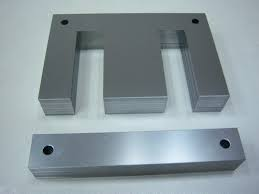
Transformer Laminations
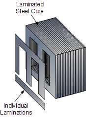
In both shell and core-type transformers, the coils are initially wound on a former, which can be cylindrical, rectangular, or oval, based on the core’s shape. To construct the laminated core, thin steel sheets are stamped into specific shapes, like “E,” “L,” “U,” and “I” forms. These stamped laminations are then assembled to create the desired core shape. For example, in a shell-type transformer, two “E” laminations and two “I” end laminations form an E-I core structure.
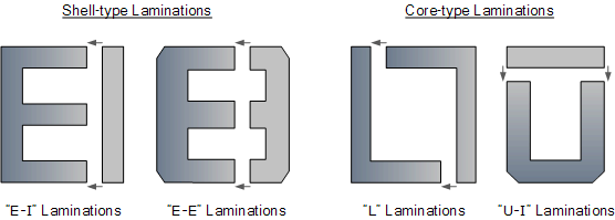
These laminations are tightly butted together to reduce air gap reluctance at the joints, allowing for high magnetic flux density. The laminations are stacked alternately, creating an overlapping joint, which further minimises flux leakage and iron losses. This construction technique helps reduce energy loss due to eddy currents and improves the efficiency of the transformer.
The E-I core laminated construction is widely used in various transformer types, including isolation, step-up, step-down, and autotransformers, due to its effective flux control and reduced core losses.
Addition of Silicon to Laminations
Electrical steel, also known as silicon steel, is a specialised steel product leveraging iron’s ferromagnetic properties for use in magnetic applications. This steel is the primary material (over 90% by volume) for soft magnetic applications.
When subjected to alternating current magnetization, electrical steel experiences two types of iron losses: hysteresis loss(from magnetic domain movement) and eddy current loss (from induced currents due to magnetic flux).
Iron provides high saturation magnetization, but it has low electrical resistance, causing high eddy current loss. Adding up to 3% silicon reduces eddy current losses by increasing electrical resistivity and improving magnetic permeability without compromising formability. Thinner sheets (0.20 to 0.65 mm) are effective in reducing eddy current loss. However, manufacturing costs and handling complexity limit thickness reduction. An insulation layer is applied to reduce eddy current losses by preventing current flow between laminated sheets.
Electrical steel is classified into two main types:
Non-Oriented Steel is suitable for applications with varying magnetic directions.
Grain-Oriented Steel is primarily used in transformers, as it aligns with unidirectional magnetization, improving efficiency.
This steel’s properties make it essential in transformer cores and other magnetic equipment where efficiency and minimise energy losses are critical.
Energy losses in transformers
In ideal transformer theory, it’s assumed that all magnetic flux generated in the primary coil perfectly links to the secondary coil, and there are no energy losses. In real-world transformers, energy losses occur in the following ways:
Coil Heating (Copper Losses) where the resistance in the coils generates heat. This loss is mitigated by cooling, typically using transformer oil.
Eddy Current Losses due to alternating magnetic fields induce currents within the core material, causing heat loss. This is minimised by using a laminated core that restricts these currents.
Hysteresis Loss where the energy is lost as heat each time the magnetic domains in the core realign with the changing magnetic field. Using a “soft” magnetic material like permalloy or silicon-iron reduces this loss. For such materials, hysteresis loss may be as low as 0.02 joules per cycle.
Despite these losses, transformers are highly efficient, often reaching up to 98% efficiency, making them among the most efficient machines. When assuming 100% efficiency in a theoretical model, all energy from the primary would be transferred to the secondary without loss, this leads to the following equation:
power in primary = power in secondary
Is/Ip = np/ns
Where: Is is the current in the secondary coil ( A), Ip is the current is the current in the primary coil (A), np is the number of turns in the primary coil, ns is the number of turns in the secondary coil.
Heating in Coils
Controlling heat in transformers is critical because excessive heat, primarily from copper loss (I²R loss), can damage the insulation system, both the paper insulation and the liquid cooling medium.
Other losses, such as hysteresis and eddy current losses, also contribute to heat generation but to a lesser extent. Without adequate cooling, overheating can lead to insulation failure and a shorter transformer lifespan.
To manage temperature and prevent thermal degradation, external transformer cooling systems are used.
Transformers heat up during operation, and effective cooling is essential to keep them efficient and reliable. Small transformers often rely on natural air circulation, while larger dry-type units may use fans to force air across their surfaces. In oil-immersed transformers, the oil acts both as insulation and a cooling medium. Basic systems use natural oil and air circulation, but as transformer size increases, fans or pumps are introduced to force oil or air flow. For very large power transformers, water-cooled heat exchangers and even directed oil systems are used to target hot spots. In some special cases, gases like hydrogen provide enhanced cooling. In short, the choice of method depends on the transformer’s size, application, and cooling demand.
Eddy Currents and Hysteresis Loss
Imagine a transformer hard at work in a power grid, tirelessly converting high voltage for efficient transmission across miles, then stepping it down to safe levels for homes and businesses. It’s designed to be remarkably efficient, but like all machines, it faces inevitable losses.
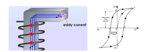
As electricity flows into the transformer’s primary winding, a portion of that power is absorbed by the core. This core, built from ferromagnetic material, is constantly responding to the alternating magnetic field, realigning its magnetic domains with each cycle. This constant shifting generates hysteresis loss, energy used up just by aligning the magnetic domains again and again. Then there’s eddy current loss: tiny currents that form within the core itself due to the fluctuating magnetic field, producing heat and wasting energy. Engineers use laminated cores to reduce these currents, but some loss is always present.
As the current flows through the windings, it encounters the winding’s internal resistance, causing copper losses (or I²R losses). These losses also generate heat, particularly under heavy loads, when current is highest, and the impact is greatest.
All these losses represent a small, yet important portion of the input power that is not converted into useful output power. Managing these losses is essential to keep the transformer running smoothly. This is why transformers are designed with cooling systems and carefully chosen materials. Even with these losses, a well-designed transformer still achieves impressive efficiency, often over 98%, making it a crucial, reliable component in the vast network that powers our world.
Copper Loss in Transformer
Copper losses in a transformer are directly related to the currents flowing through the primary and secondary windings and the internal resistance of each winding. These losses are given by:
Primary Copper Loss: I12R1, where I1 is the primary current and R1 is the resistance of the primary winding.
Secondary Copper Loss: I22 R2, where I2 is the secondary current and R2 is the resistance of the secondary winding.
Since both I1 and I2 depend on the transformer’s load, the copper losses vary with the load. As the load increases, the current through each winding rises, leading to higher copper losses. This variation means that copper loss is highest when the transformer operates under full load and lowest at no load. Managing these load-dependent losses is crucial for efficient transformer operation, as excessive copper losses can cause overheating and impact the transformer’s longevity and performance.
Copper loss can simply be denoted as,
IL2R2′ + Stray loss
Where, IL = I2 = load of transformer, and R2′ is the resistance of the secondary transformer.
Stray losses in a transformer occur due to leakage flux and the magnetic field surrounding the transformer components. These losses are found in various parts of the transformer, including the windings, clamping structures, and the tank. Stray losses arise as leakage flux interacts with nearby metallic parts, inducing currents that produce heat and contribute to energy loss.
The magnitude of these losses depends on the distance between the source of leakage flux and the surrounding metallic parts. Stray losses are inversely proportional to the gap between the leakage flux source and the metallic parts, meaning, as the distance between them increases, stray losses decrease. Therefore, transformer design aims to manage the paths of leakage flux and carefully position metallic parts to minimise stray losses, enhancing overall efficiency and reducing unwanted heating.
Core Losses in Transformer
Both Hysteresis loss and eddy current loss depend upon magnetic properties of the materials used to construct the core of the transformer and its design.
These losses in transformers are fixed and do not depend upon the load current, they are also known as iron loss in transformers can be considered as constant for all ranges of load.
Hysteresis loss in transformer is denoted as,
Wh = Khf(Bm)1.6 Watts
Eddy current loss in a transformer is denoted as,
Wc = Kcf2Kf2Bm2 Watts
Where, Kh = Hysteresis constant. ( J/m3) Ke = Eddy current constant (A) .Bm is the maximum magnetic flux density (Wb/m2) and f is the frequency ( Hertz).
Eddy current loss, while a natural consequence of AC in the transformer, is managed by constructing the core from laminated sheets, reducing the paths for these currents and minimising energy wasted as heat. This simple approach helps to improve the overall efficiency of the transformer.
Reluctance
In magnetic circuits, reluctance is the opposition to magnetic flux, similar to electrical resistance in an electric circuit. Reluctance increases with the length of the magnetic path (l). A longer path makes it harder for the magnetic flux to flow, just as a longer conductor increases electrical resistance. Reluctance decreases as the cross-sectional area (A) of the core increases. A larger area allows more flux to pass through, reducing opposition.
Reluctance decreases as permeability(µ) increases. Materials with higher permeability allow more flux to flow, which reduces reluctance. Permeability represents a material’s ability to support magnetic flux, and as µ increases, the material becomes a better path for flux.
Therefore, reluctance (Rm) can be minimised by reducing the length of the magnetic path, increasing the core’s cross-sectional area, or using materials with high permeability. This helps achieve a more efficient magnetic circuit by allowing more magnetic flux to flow with less opposition.
Relative and Absolute Permeability
Permeability μ describes how easily a material supports the flow of magnetic flux. It’s often expressed as:
μ = μ0μr
where: μ0 is the absolute permeability of free space (air or vacuum), with a value of 4πx10-7 H/m or approximately 1.256637061 x 10⁻⁶ H/m and μr is the relative permeability of a material, indicating how many times the material’s permeability is greater than that of free space.
Relative permeability μr simplifies calculations by expressing permeability as a ratio. Free space has a relative permeability of 1, while materials with higher μr (like iron) have a much greater permeability, significantly enhancing magnetic flux. For example, if a material has a relative permeability of 1000, it can support magnetic flux a thousand times more effectively than free space.
Because iron and similar materials have high relative permeabilities, they are commonly used in transformer and inductor cores to increase magnetic flux and improve efficiency.
The effects of the environment on Transformers.
Extreme climates can significantly affect the performance, reliability, and lifespan of transformers. Transformers are critical components in electrical systems, and their operation is highly dependent on environmental conditions.
High-Temperature Environments: High ambient temperatures can lead to overheating, reducing the efficiency and lifespan of the transformer insulation system and other components. Prolonged exposure to high temperatures accelerates the aging of insulation, potentially leading to dielectric failure. Cooling systems may need to work harder, increasing energy consumption and maintenance requirements. Repeated thermal expansion and contraction can lead to mechanical stresses, weakening structural integrity. In oil-filled transformers, high temperatures can degrade insulating oil, reducing its dielectric strength and cooling efficiency.
Low-Temperature Environments: In oil-filled transformers, extremely low temperatures can cause insulating oil to thicken, reducing its ability to flow and dissipate heat efficiently. If oil solidifies, cooling pathways can be obstructed, leading to localized overheating. Metal and other materials used in transformers may become brittle at low temperatures, increasing the risk of mechanical failure. Cold temperatures can make startup more challenging as initial currents may be higher due to cold oil and increased resistance.
High-Humidity Environments: High humidity can lead to moisture ingress into the transformer. Moisture reduces the dielectric strength of insulating materials. Metal components, such as windings and tanks, are prone to corrosion in humid environments. The presence of moisture increases the likelihood of partial discharges, which can degrade insulation over time.
Arid Environments: Transformers in desert climates may be exposed to dust and sand infiltration. Dust can obstruct cooling fins and fans. Accumulated dust can lead to surface discharge and hotspots. High daytime temperatures and low night time temperatures in arid regions can cause thermal cycling, leading to mechanical stress.
Coastal Environments: Coastal areas have high salt content in the air, leading to corrosion of metal components. Salt contamination can create conductive paths, leading to leakage currents and potential short circuits. Combined effects of humidity and salt can lead to accelerated aging of insulating materials.
Severe Weather Conditions: Lightning strikes can cause surges, leading to insulation breakdown or winding damage. Adequate surge arresters are necessary in areas prone to lightning. Floodwaters can submerge transformers, leading to insulation failure, corrosion, and contamination of insulating oil. High winds can damage external components, such as cooling fans and radiators, or deposit debris that obstructs cooling systems.
Possible solutions.
- Cooling Systems: Use advanced cooling techniques, such as forced air or water cooling, in high-temperature areas.
- Dehumidification: Install dehumidifiers or silica gel breathers to manage humidity levels.
- Corrosion Protection: Apply anti-corrosion coatings and use stainless steel components in coastal environments.
- Enhanced Insulation: Use high-performance insulating materials to withstand extreme thermal and electrical stresses.
- Regular Maintenance: Frequent inspections and maintenance to detect and address potential issues early.
By addressing these environmental challenges, transformers can be better protected, ensuring reliable operation even in extreme climates.
Interested in our Electrical Engineering Courses?
At iLearn Engineering®, we offer a diverse range of online accredited engineering courses and qualifications to cater to different academic and career goals. Our courses are available in varying credit values and levels, ranging from 40 credit Engineering Diplomas to a 360 credit International Graduate Diploma.
Short Courses (40 Credits)
A selection of our more popular 40 credit electrical diplomas…
Diploma in Electrical and Electronic Engineering
Diploma in Electrical Technology
Diploma in Renewable Energy (Electrical)
First Year of Undergraduate Electrical (Level 4 – 120 Credits)
Higher International Certificate in Electrical and Electronic Engineering
First Two Years of Undergraduate Electrical (Level 5 – 240 Credits)
Higher International Diploma in Electrical and Electronic Engineering.
Degree equivalent Graduate Diploma Electrical (Level 6 – 360 Credits)
International Graduate Diploma in Electrical and Electronic Engineering
All Electrical and Electronic Courses
You can read more about our selection of accredited online Electrical and Electronic Engineering courses here.
Complete Engineering Course Catalogue (all courses including industrial, mechanical and computer engineering)
Alternatively, you can view all our online engineering courses here.
Recent Posts
Civil Engineering Courses and Diplomas: Topics, Skills and Career Routes
Civil Engineering Courses and Diplomas: Topics, Skills and Career Routes Introduction Civil engineering is the backbone of modern society. From roads and bridges to skyscrapers and water systems, civil engineers design, build, and maintain the infrastructure that keeps the world running. If you’re considering a civil engineering course or diploma, understanding what it covers is […]
What Is a Diploma in Engineering? Courses, Levels and Career Routes Explained
What Is a Diploma in Engineering? Courses, Levels and Career Routes Explained Introduction Engineering shapes the world around us, from the buildings we live in to the technology we use every day. But for many aspiring engineers, the biggest question is not whether to pursue engineering, but how to start. Traditional university degrees are not […]
Engineering Courses: How to Choose the Right Route for Your Career
Engineering Courses: How to Choose the Right Route for Your Career Introduction Choosing an engineering course can feel like standing at the beginning of several different roads, each leading towards a different kind of future. One route may lead into mechanical systems and manufacturing. Another may lead towards aircraft, infrastructure, electronics, computing, renewable energy or […]