Inside the Machines: Understanding the Construction of Induction and Synchronous Motors
Summary
Electric motors lie at the heart of countless machines — from household appliances to industrial drives. But what really goes on inside those motors? In this post, we dive into the construction and inner workings of induction and synchronous motors, unraveling:
- The fundamental components — stator, rotor, windings, air gap, and housing
- How induction motors generate torque without direct electrical connection to the rotor
- What makes synchronous motors lock onto a fixed speed and maintain synchronism
- Key design choices and trade-offs shaping motor efficiency and power capability
Whether you’re studying electric machinery or designing one, you’ll come away with a clearer understanding of how these motors are built and why they perform the way they do.
Introduction
A synchronous machine is a device that can function as a generator or a motor. Its defining characteristic is that the magnetic field within the machine remains constant, and its armature handles alternating current (AC) in perfect synchronisation with the machine’s rotational motion. The AC frequency produced (in a generator) or consumed (in a motor) by the machine is directly proportional to the machine’s speed and the number of pole pairs in the magnetic field.
Examples include as a generator which is commonly used in power plants (e.g., alternators in hydropower and thermal plants), and as a motor used in applications requiring precise speed regulation (e.g., industrial drives, pumps, and compressors).
Synchronous machines are vital in systems where constant speed or precise frequency control is required.
Synchronous motors run at synchronous speed. The synchronous speed is given by
Ns = 120f / p
Where, Ns = synchronous speed (rpm), f = supply frequency (Hz) and p = number of poles.
As we can see from the equation, the synchronous speed depends on the frequency of the supply and the number of poles.
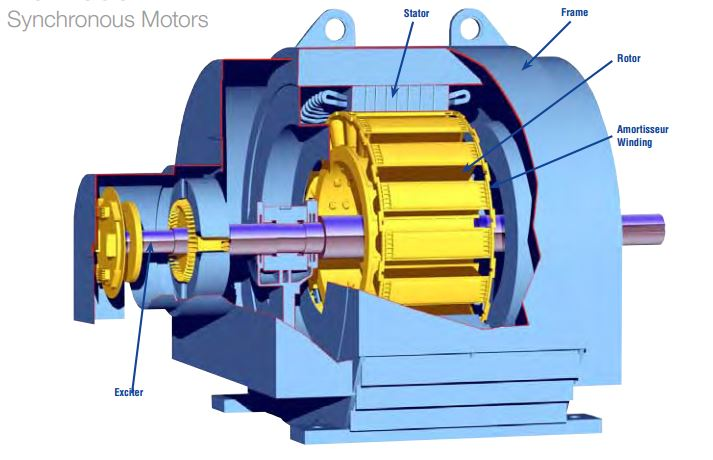
The construction of a synchronous motor is very similar to that of a synchronous generator (alternator). With the primary difference being their application, one converts electrical energy into mechanical energy (motor), and the other does the reverse (generator). Like any electric motor, the synchronous motor consists of two main parts:
Stator
The stationary part of the motor consists of a frame and a core made up of laminated steel sheets to reduce eddy current losses. The core has slots that house the armature windings, which produce a rotating magnetic field when powered by AC.
These windings can be single-phase or three-phase, with enamelled copper commonly used for its high conductivity and insulation properties.
In the case of three-phase windings, they are distributed across multiple slots to achieve a sinusoidal EMF distribution, reducing harmonics and improving efficiency. This design ensures smooth operation, better torque, and compatibility with standard AC systems. The stator’s construction is critical for the machine’s reliable and efficient performance.
Rotor
The rotor is the rotating part of the machine, we are going to focus on the main types.
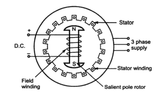
Salient Pole Rotor:
Used in low-speed applications (e.g., hydroelectric generators) and features large poles that protrude from the rotor.
The rotor of a salient pole synchronous machine is characterised by poles that project outward from the rotor surface. It is constructed using steel lamination to minimise eddy current losses.
The air gap between the stator and rotor is non-uniform, largest between the poles and smallest at the pole centres.This design helps focus the magnetic flux at the pole centres for efficient operation.
Salient pole machines are designed for medium and low speed operations.They typically have a large number of poles, which allows them to operate at low rotational speeds while maintaining the required synchronous speed for a given frequency (example: hydroelectric generators).
The damper windings are embedded in the rotor near the pole faces to assist in starting the motor, especially since synchronous motors cannot self-start and suppress oscillations or vibrations during transient conditions, improving stability.
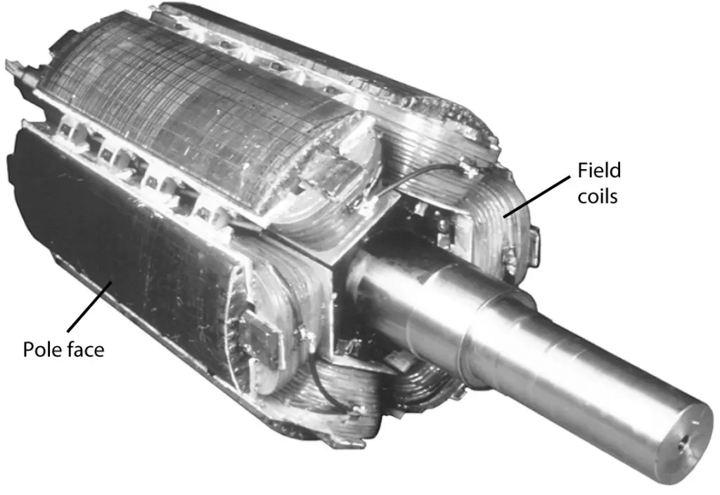
Cylindrical Rotor (Non-Salient Pole)
The cylindrical rotor, also known as a non-salient pole rotor, is designed for high-speed applications and has distinct structural and operational characteristics.
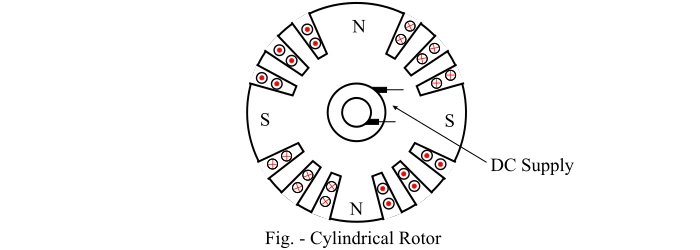
They are constructed from solid forgings of high-grade nickel-chrome-molybdenum steel for strength, durability, and excellent magnetic properties.Unlike salient pole rotors, the poles in a cylindrical rotor are not physically projecting. Magnetic poles are created by current flowing through rotor windings, which are embedded in slots along the rotor’s surface.
The rotor has a uniform air gap, which contributes to reduced noise, lower windage losses (friction caused by air resistance).Improved balance, making it suitable for high-speed operation.
They are typically used in high-speed applications (e.g., steam turbines in thermal and nuclear power plants)., they operate with fewer poles (usually 2 or 4 poles) due to the high rotational speeds required.
A DC supply is provided to the rotor windings through slip rings and brushes.Once energised, the rotor windings generate magnetic poles that interact with the stator’s rotating magnetic field.
Cylindrical rotors are commonly used in turbo-generators, where efficiency, speed, and smooth operation are critical.
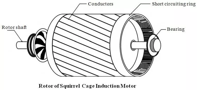
Squirrel Cage Rotor
The squirrel cage rotor is a common type of rotor used in induction motors, with a simple and rugged design.
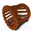
The rotor consists of copper or aluminium bars embedded in semi-closed slots of a laminated rotor core. The rotor bars are short-circuited at both ends using end rings, forming a closed circuit. The core is made of laminated steel to reduce eddy current losses and improve efficiency. There are no discrete windings on the rotor; the induced currents in the bars create the magnetic field.
The rotor does not have a fixed number of poles as they are induced automatically through electromagnetic induction based on the stator’s magnetic field. The absence of traditional windings leads to low leakage reactance which results in low starting torque but allows for high running torque once the motor reaches operating speed. The starting torque is low because the rotor bars are short-circuited by the end rings, preventing any external resistance from being added.
Higher resistance in the rotor circuit would improve starting torque, but this modification is not possible with a standard squirrel cage rotor. The rotor provides excellent running performance with high efficiency and good speed regulation.
Drawbacks of Squirrel Cage Rotor The lack of external rotor resistance results in limited torque during startup. Large inrush currents are drawn during starting, which can strain the electrical system. At startup, the power factor is low due to the high reactive power drawn by the motor.
Improving Starting Characteristics While the inherent design of the squirrel cage rotor limits the ability to insert resistance directly, modifications in circuit design can partially improve its starting performance: Skewing the rotor bars reduces noise and improves starting characteristics. Changing the material of the rotor bars to increase resistance can enhance starting torque.
Soft starters or variable frequency drives (VFDs) can control the voltage and frequency supplied to the motor, reducing inrush currents and improving startup performance.
Wound Type Rotor or Slip Ring Type Rotor
Wound Rotor (Slip Ring Rotor) are made from laminated cold-rolled grain-oriented silicon steel to minimise eddy current losses and hysteresis losses, they have distributed and Short-Pitched Winding to ensure that the generation of a sinusoidal emf output. The number of rotor poles must match the number of stator poles, as the induction motor won’t function with unequal poles, the rotor does not adjust automatically to the stator pole changes.
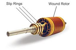
The Three-Phase Rotor Winding must be connected in a star configuration, regardless of the stator winding configuration (star or delta).They are equipped with slip rings made of phosphorous bronze or brass for connecting rotor windings to external circuits. Brushes, often made of carbon (preferred for self-lubricating and low-friction properties), connect the slip rings to the external resistors. External resistors connected through the slip rings improve starting torque and limit starting current, these resistors enhance the motor’s power factor during start-up.
Excellent starting performance due to the inclusion of external resistance. Running performance, however, is relatively poor compared to a squirrel cage rotor due to increased losses and mechanical complexity, but they can have external circuit connections and better starting characteristics
Applications: Slip ring motors are commonly used in applications requiring: High starting torque (e.g., cranes, lifts, conveyors) or variable speed (achieved by adjusting external resistance).
The wound rotor design’s main trade-off is between its improved starting performance and its less efficient running performance due to added resistive losses.
General characteristics of Synchronous Motors:
- The rotor requires a DC excitation to create a magnetic field.
- Operates at a constant speed (synchronous speed), determined by the supply frequency and number of poles.
- It often requires auxiliary means (e.g., pony motors or damper windings) to start, as it cannot self-start like an induction motor.
Comparison with Alternator Construction:
Similarities are that they both have a stator and rotor. They both require a DC excitation system for the rotor.
Differences are that In alternators, the rotor is driven by a prime mover to generate electrical power, while in synchronous motors, the rotor is driven by the electromagnetic interaction to produce mechanical power. Synchronous motors often include additional features like starting mechanisms (e.g., damper windings) to handle the initial non-synchronous operation.
This construction enables the synchronous motor to operate efficiently in applications requiring constant speed under varying load conditions.
Interested in our Electrical Engineering Courses?
At iLearn Engineering®, we offer a diverse range of online accredited electrical engineering courses and qualifications to cater to different academic and career goals. Our courses are available in varying credit values and levels, ranging from 40 credit Engineering Diplomas to a 360 credit International Graduate Diploma.
Short Courses (40 Credits)
A selection of our more popular 40 credit electrical diplomas…
Diploma in Electrical and Electronic Engineering
Diploma in Electrical Technology
Diploma in Renewable Energy (Electrical)
First Year of Undergraduate (Level 4 – 120 Credits)
Higher International Certificate in Electrical and Electronic Engineering
First Two Years of Undergraduate (Level 5 – 240 Credits)
Higher International Diploma in Electrical and Electronic Engineering.
Degree equivalent Graduate Diploma (Level 6 – 360 Credits)
International Graduate Diploma in Electrical and Electronic Engineering
All Electrical and Electronic Courses
You can read more about our selection of accredited online Electrical and Electronic Engineering courses here.
Complete Engineering Course Catalogue (all courses)
Alternatively, you can view all our online engineering courses here.
Recent Posts
Understanding Key Performance Indicators in Manufacturing
Understanding Key Performance Indicators in Manufacturing Introduction Key Performance Indicators (KPIs), or sometimes written as Key Performance Measures, are some of the key ‘metrics’ that are used to measure the performance of an industrial system. A good KPI for a manufacturing system should be SMART, that is: Specific – It should measure a specific output […]
How Aircraft Structures Evolved: From Fragile Flyers to Engineering Masterpieces
How Aircraft Structures Evolved: From Fragile Flyers to Engineering Masterpieces Introduction As with all other aspects involved with an aircraft, the structural design and layout has changed markedly over the history of flight, in line with technological advances and new discoveries. This section will highlight some of the more substantial developments made during the history […]
Why Lean Manufacturing Matters: Principles of waste
Why Lean Manufacturing Matters: Principles of waste Introduction Lean manufacturing isn’t just a toolkit for improving efficiency, it’s a mindset that reshapes how organisations think about value. At its core, lean focuses on delivering exactly what the customer needs, when they need it, with as little waste as possible. In an increasingly competitive and resource-conscious […]