Mastering Motor Calculations: A Practical Guide to Synchronous Machines
Introduction
Understanding how to calculate the performance of motors and synchronous machines is essential for every electrical engineer. From determining torque and power to analysing efficiency and speed regulation, accurate calculations form the backbone of reliable design and operation. In this guide, we’ll break down the key formulas, concepts, and practical examples you need to confidently master motor and synchronous machine calculations.
Voltage
Ohm’s Law states that current through the conductor is directly proportional to applied voltage and is expressed as:
I = V / R
where : I is the current, measured in amperes (A); V is the applied voltage, measured in volts (V); R is the resistance, measured in ohms (Ω).
You can calculate the resistance of your motor by measuring the consumed current and applied voltage. For any given resistance (in the motors it is basically the resistance of the coil) this formula explains that the current can be controlled by applied voltage.
Example: If V is 40 volts and R is 500 ohms: what is the current?
Solution:
Use V = I R rearranging gives I = V/R
I = 40>/500 = 0.08 amps.
Power
The consumed electrical power of the motor is defined by the following formula:
Pin = I x V
where : Pin is the input power, measured in watts (W); I is the current, measured in amperes (A); V is the applied voltage, measured in volts (V).
Example: A DC electric motor transforms 1.50 kW of electrical power into mechanical form. If the motor’s operating voltage is 300 volts, how much current does it “draw” when operating at full load (full power output)?
Solution:
First we must change 1.5kW to 1500W
using P = IV where P = 1500W and V = 300V
I = 1500/300 = 5A
he power of a motor is determined by its speed and torque, using the following formula
Pout = τ x ω
where : Pout is the output power, measured in watts (W); τ is the torque, measured in Newton metres (Nm); ω is the angular speed, measured in radians per second (rad/s).
Example: A motor provides a torque of = 24.525 Nm, and rotates at 5.25 rad/sec, calculate the output power
Solution:
Pout = τ x ω
Pout = 24.525 x 5.25 = 128.76W
Angular Speed
It is easy to calculate angular speed if you know rotational speed of the motor in revolutions per minute (rpm):
ω = rpm x 2π / 60
where: ω is the angular speed, measured in radians per second (rad/s); rpm is the rotational speed in revolutions per minute;(rev/min) π is the mathematical constant pi (3.14). 60 is the number of seconds in a minute.
Example 1: What is 50 rev/ min as angular speed
Solution:
ω = rpm x 2π / 60
ω = 50 x 2π /60
ω = 5.25 rad/sec
Example 2: if the angular speed is 4.5 rad/sec what is its rotational speed in rev/min
Solution:
ω = rpm x 2π / 60
4.5 = rpm x 2π / 60
4.5 x 60 / 2π = rpm
= 42.97 rev/ min
Efficiency
Motors that are 100% do not exist, as this would mean that all electrical power is converted to mechanical energy. The maximum achievable efficiency is 50-60%.
Efficiency of the motor is calculated as mechanical output power divided by electrical input power, it has no units.
E = Pout / Pin
Example 1: if the pin = 1.5kW and the P out = 128.76W, calculate the efficiency
Solution:
E = 128.76 / 1500 = 0.0858
to get % we multiply by 100
% Efficiency = 8.58%
Example 2: if the % efficiency is 9.4% and the Pin is 1300W, what is the Pout
Solution:
Firstly we need to change 9.4% to a decimal so we divide it by 100 = 0.094
E = Pout / Pin
0.094 = Pout / 1300
Pout = 0.094 x 1300
Pout = 122.2W
Torque
To measure the torque of a motor is very complex and requires specialist equipment so it is usually a quantity that is calculated.
Pout = Pin x E
if we substitute for power using the previous sections we get
τ x ω = I x V x E
τ x rpm x 2π / 60 = I x V x E
and the formula for calculating torque will be
τ = (I x V x E x 60) / (rpm x 2π)
If there is no load, there is no torque.
All of the quantities required can be measured using standard equipment.
A typical estimate of 15% efficiency represents maximum efficiency of the motor which occurs only at a certain speed. Efficiency may be anywhere between zero and the maximum; in our example below 1000 rpm may not be the optimal speed so for the sake of calculations you may use 10% efficiency (E = 0.1as a decimal instead of a percentage).
Example: if the speed is 1000 rpm, voltage is 6 Volts, and current is 220 mA (0.22 A), efficiency = 0.1. Calculate the torque
Solution:
τ = (I x V x E x 60) / (rpm x 2π)
τ = (0.22 x 6 x 0.1 x 60) / (1000 x 2 x 3.14) = 0.00126 Nm
As the result is small, it is expressed in milliNewton metres (mNm). There is 1000 mNm in 1 Nm, so the calculated torque is 1.26 mNm. It could be also converted further to still common gram force centimetres (g-cm) by multiplying the result by 10.2, i.e. the torque is 12.86 g-cm.
In our example input electrical power of the motor is 0.22 A x 6 V = 1.32 W, output mechanical power is 1000 rpm x 2 x 3.14 x 0.00126 Nm /60 = 0.132 W.
Torque calculation accuracy depends on precise measurement of voltage, current, and speed, but is heavily influenced by the motor’s efficiency. Efficiency is impacted by factors like assembly quality, sensor alignment, friction, and axle alignment.
In small motors, speed and current exhibit a linear relationship with torque, making it possible to plot their graphs with just two measurements. However, efficiency and power are non-linear, requiring more data points for accurate representation. Key characteristics of small motors include:
Maximum Power: Typically occurs at approximately 50% of stall torque, corresponding to about 50% of no-load speed.
Maximum Efficiency: Usually achieved at 10-30% of stall torque, which aligns with 70-90% of no-load speed.
This highlights the importance of understanding the distinct behaviours of these parameters to accurately analyse motor performance.
Inertia
Different objects have unique moments of inertia, which depend on their mass, dimensions (such as radius or length), and the axis of rotation. The following equations illustrate how to calculate the moment of inertia for various objects.
For simplicity, the axis of rotation is assumed to pass through the centre of the object or along its central axis.
Hoop about the central axis I = M x R2
Where I is the moment of inertia(kgm2), M is mass (kg), and R is the radius of the object.(m)
Annular cylinder (or ring) about the central axis: I = ½ M ( R12 + R22)
Where I is the moment of inertia, M is mass, R1 is the radius to the left of the ring, and R2 is the radius to the right of the ring.
Solid cylinder (or disk) about the central axis: I = ½ M x R2
Where I is the moment of inertia, M is mass, and R is the radius of the object
Thin-shelled hollow sphere I = ⅔ x M x R2
Solid sphere I = ⅖ x M x R2
Energy and Inertia
Energy is measured in joules (J), while the moment of inertia is measured in kgm2m2 (kilograms times metres squared). A useful way to understand the relationship between moment of inertia and energy is by exploring physics problems, such as the examples below:
Example: Calculate the moment of inertia of a disk that has a kinetic energy of 24,400 J when rotating 602 rev/min.
Solution: The first step in solving this problem is to convert 602 rev/min to SI units. To do this, 602 rev/min has to be converted to rad/s. In one complete rotation of a circle is equal to 2π rad, which is one revolution and 60 seconds in a minute. Remember the units must cancel out to get rad/s.
ω = 602×2π/ 60 =63 rad/s
The moment of inertia for a disk as seen in the previous section is I = ½ x M x R2
Since this object is rotating and moving, the wheel has kinetic energy or the energy of motion. The kinetic energy equation is as follows:
KE = ½ x I x ω2
Where KE is kinetic energy, I is the moment of inertia, and ω is the angular velocity which is measured in rad/s.
KE is 24,400 J and 63 rad/s for angular velocity into the kinetic energy equation.
24400 = ½ x I x 632
24400 x 2 / 632 = I
I = 12.3kgm2
Inertial Load: The inertia of an object refers to its resistance to changes in its motion or position. Inertia is directly proportional to the object’s mass or, if the object is in motion, to its velocity. According to Newton’s first law of motion, an object will continue to move at a constant velocity unless acted upon by an external force. Similarly, an object at rest will remain at rest until a force causes it to move.
EMF Equation of a DC Motor
Earlier in the workbook we introduced the basic DC motor’s E.M.F equation is given below.
Eb = PΦNZ / 60A
Where; P is the number of poles, Ф is the Flux per pole (Wb), N is the Speed of motor in (RPM), Z is the Number of conductors, A is the Number of parallel paths
Since P,Z and A are fixed then we can simplify the equation
Eb ∝ ΦN
Eb = kΦN
Where k is the proportionality constant
Alternative calculation
The back EMF of DC motor equation can also be defined as
Eb = V – IaRa
Where; V is the supply voltage(V), Ia is the Armature current (I), Ra is the Armature resistance(Ω)
If we combine the equations we get:
kΦN = V – IaRa
k = N = V – IaRa / ΦN
The above relation shows that the speed of a DC motor can be controlled through change in voltage, flux and armature resistance.
Example: A 220 V shunt motor has armature and field resistance of 0.2 Ω and 220 Ω respectively. The motor is driving a constant load torque and running at 1000 rpm drawing 10 A current from the supply. Calculate the new speed and armature current if an external armature resistance of value 5 Ω is inserted in the armature circuit. Neglect armature reaction and saturation
Solution The circuit diagram of the shunt motor is:
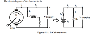
For initial operating point: IL1 = 10 A, ra = 0.2 Ω and supply voltage V = 220 V.
Field current If1 = 220/220 = 1A
Armature current Ia1 = 10A – 1A = 9A
Now we write down the expressions for the torque and back emf.
Te1 = kt If1 Ia1 = kt × 1 × 9 = TL
Eb1 = kg If1 n = kg × 1 × 1000 = V – Ia1 ra = 220 – 9 × 0.2
= 218.2V kg × 1 × 1000 = 218.2V
Since field resistance remains unchanged If2 = If1 = 1 A.
Let the new steady armature current be Ia2 and the new speed be n2.
In this new condition the torque and back emf equations are
Te2 = kt ×1 × Ia2 = TL Eb2 = kg × 1 × n2 = V – Ia2(ra + Rext)
∴kg × 1 × n2 = 220 – Ia2 × 5.2 V
Taking the ratios of Te2 and Te1
Te2 / Te1 = kt x 1 x Ia2 / kt x 1 x 9
Thus Ia2 = 9 A
Now taking the ratio emfs Eb2 / Eb1
kg x 1 x n2 /kg x 1 x 1000 = 220 – Ia2 x 5.2/ 218.2
n2 / 1000 = 220 – 9 x 5.2/ 218.2
n2 = (173.2 x 1000) / 218.2
n2 = 793.76 rpm
Interested in our Electrical Engineering Courses?
At iLearn Engineering®, we offer a diverse range of online accredited electrical engineering courses and qualifications to cater to different academic and career goals. Our courses are available in varying credit values and levels, ranging from 40 credit Engineering Diplomas to a 360 credit International Graduate Diploma.
Short Courses (40 Credits)
A selection of our more popular 40 credit electrical diplomas…
Diploma in Electrical and Electronic Engineering
Diploma in Electrical Technology
Diploma in Renewable Energy (Electrical)
First Year of Undergraduate (Level 4 – 120 Credits)
Higher International Certificate in Electrical and Electronic Engineering
First Two Years of Undergraduate (Level 5 – 240 Credits)
Higher International Diploma in Electrical and Electronic Engineering.
Degree equivalent Graduate Diploma (Level 6 – 360 Credits)
International Graduate Diploma in Electrical and Electronic Engineering
All Electrical and Electronic Courses
You can read more about our selection of accredited online Electrical and Electronic Engineering courses here.
Complete Engineering Course Catalogue (all courses)
Alternatively, you can view all our online engineering courses here.
Recent Posts
Civil Engineering Courses and Diplomas: Topics, Skills and Career Routes
Civil Engineering Courses and Diplomas: Topics, Skills and Career Routes Introduction Civil engineering is the backbone of modern society. From roads and bridges to skyscrapers and water systems, civil engineers design, build, and maintain the infrastructure that keeps the world running. If you’re considering a civil engineering course or diploma, understanding what it covers is […]
What Is a Diploma in Engineering? Courses, Levels and Career Routes Explained
What Is a Diploma in Engineering? Courses, Levels and Career Routes Explained Introduction Engineering shapes the world around us, from the buildings we live in to the technology we use every day. But for many aspiring engineers, the biggest question is not whether to pursue engineering, but how to start. Traditional university degrees are not […]
Engineering Courses: How to Choose the Right Route for Your Career
Engineering Courses: How to Choose the Right Route for Your Career Introduction Choosing an engineering course can feel like standing at the beginning of several different roads, each leading towards a different kind of future. One route may lead into mechanical systems and manufacturing. Another may lead towards aircraft, infrastructure, electronics, computing, renewable energy or […]