Safety Challenges in Industrial Robotics
Introduction
Automation has improved efficiency and safety in manufacturing, handling repetitive and hazardous tasks. However, it also brings safety concerns for workers, including risks from physical accidents, system failures, human error, and cybersecurity threats. To address these, companies use advanced safety protocols, sensors, automated stop features, and collaborative robots that can safely work alongside humans.
According to OSHA, the most common hazards involving robots in the workplace often occur during non-routine tasks, such as programming, maintenance, repair, testing, and setup. These tasks require close interaction with robots, which increases the risk of accidents. OSHA identifies seven main potential hazards for humans working with robots:
Human Errors: Mistakes during setup or programming can lead to unintended robot actions, causing injuries.
Control Errors: Issues in the robot’s control system, like software or electrical malfunctions, can result in unexpected movements.
Unauthorised Access: Workers entering restricted areas or bypassing safety protocols face higher risks of accidents.
Mechanical Failures: Mechanical issues, such as component wear or failure, can lead to unpredictable and dangerous behaviour.
Environmental Sources: External factors, like power surges or interference from other equipment, may impact robot operations.
Power Systems: Malfunctions in power sources or connections may cause sudden or uncontrolled movements.
Improper Installation: Incorrect setup of robots or safety systems can compromise operational safety, increasing the likelihood of incidents.
Addressing these hazards requires strict adherence to safety protocols, proper training, and ongoing monitoring of robotic systems to ensure worker safety.
Mechanical Hazards
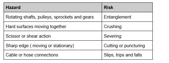
When assessing machinery and equipment for potential mechanical hazards, it’s essential to consider the following aspects of moving parts that may cause injury:
Point of Operation: This is where the machine performs work on the material, such as cutting, shaping, or forming. Exposure to this area can result in significant injury.
Power Transmission Parts: Components like belts, chains, pulleys, and gears that transfer energy from the power source to the machine’s moving parts can be hazardous if not shielded properly.
Moving Parts Hazard Areas: All parts of the machine that move, including rotating, reciprocating, or traversing parts, can pose risks. Contact with these moving parts may lead to cuts, crushing, or amputation injuries.
Entanglement Risks: Parts that move in a way that could catch clothing, hair, or body parts, such as rotating shafts or spindles, should be evaluated for their potential to cause entanglement injuries.
Impact Hazards: Moving parts that may strike a person, such as swinging arms or mechanisms that return suddenly, need to be considered, especially if they operate near or above workers.
Pinch Points: Areas where two parts move together or where one part moves toward a stationary object can create crushing hazards. Workers may get caught in these points if they are not adequately guarded.
Shear Points: Locations where two machine parts pass closely, or one moves past a fixed object, can shear or cut body parts.
Ejection of Parts or Material: Machines that eject parts, workpieces, or materials can create hazards if the expelled objects are not contained or directed safely.
Effective risk assessments of machinery and equipment should evaluate these hazards and implement controls, such as guards, barriers, and emergency stops, to ensure worker safety.
Risk control of mechanical hazards
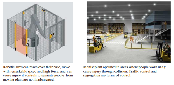
Factories use separation to protect workers from machinery hazards through three main methods:
Distance Separation: keeps workers out of reach from dangerous equipment, including those accessing elevated areas.
Barrier Separation: involves guards or shields around machines to prevent contact and control debris.
Time Separation: restricts worker access to machines only during designated downtimes, ensuring equipment is disabled for safe maintenance.
These layered controls help maintain a safer environment by minimising direct exposure to machinery risks.
Guarding
There are four main types of machine guards commonly used to protect workers from hazards:
Fixed Guards: These are permanent barriers that provide the highest level of protection by enclosing dangerous areas. Fixed guards are sturdy and reliable, as they don’t require frequent adjustment or maintenance, making them ideal for consistently hazardous areas. Typical examples include a fixed guard on a belt sander, covering the belt and pulley to prevent accidental contact and fencing around industrial robots to prevent entry into the robot’s operational area.

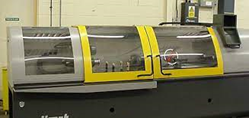
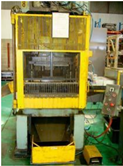
Interlocking Guards: These guards are designed to automatically shut down a machine if the guard is opened or removed. Interlocking guards prevent access to dangerous areas while the machine is in operation, only allowing access once the machine has come to a complete stop. Typical examples include a CNC machine, an interlocking guard prevents the machine from operating if the door is open, protecting the worker from rotating parts and tool movement, and a hydraulic press prevents operation until all guards are in place.
Adjustable Guards: These guards can be manually adjusted to fit different sizes of material or workpieces. They allow some flexibility for various tasks while still providing a protective barrier, though they may require frequent adjustments and checks for safety. Typical examples include on a drill press that can be positioned to shield the drill bit and prevent hand contact and on a table saw, allowing operators to adjust for different cutting depths while covering the blade.
Self-Adjusting Guards: These guards automatically move or adjust according to the size and position of the material entering the danger zone. Self-adjusting guards provide protection by creating a barrier around the area of operation only when needed, retracting when it’s safe. Typical examples include on a circular saw that covers the blade when not in use but lifts as wood is fed in, and on a radial arm saw, which slides to cover the blade when the saw arm is retracted.
Locking systems
For access panels or doors with interlocking devices that permit access to mechanical parts that continue to move after the energy source is shut off, incorporating a delay mechanism is essential for safety. This delayed-release mechanism ensures that the door or panel does not immediately unlock when the power is cut, allowing time for any residual motion in the machinery to completely stop.
Captive key systems are a safety mechanism used to ensure that certain steps are followed in a set sequence before access to hazardous machinery or equipment is granted. These systems rely on a series of mechanical keys that are “captive” in a lock until specific conditions are met, ensuring that machinery is safely powered down and isolated before maintenance or entry.
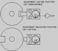
How Captive Key Systems Work?
The system requires a series of actions in a predetermined sequence. Each step locks or releases a key only when it’s safe to proceed. For example, to access a dangerous area, the machine must first be powered down. Turning off the power releases a key that can then be used to unlock an access door or panel. Once the machinery is isolated, a key is used to unlock the access point. The system ensures that the access point remains locked until the machine is safely powered down and isolated from its energy sources. Captive key systems are widely used in industries with high-risk machinery, such as manufacturing, power generation, and chemical processing, where strict safety controls are critical to worker protection.
Electrical and Thermal Hazards
Workers performing tasks like maintenance, repair, installation, service, and cleaning around machinery are at high risk of injury or fatality due to potential accidental machine activation. This risk is increased by their close proximity to equipment, the chance of accidental activation from bumped controls or system failures, and possible lack of hazard awareness. Essential safety measures include Lockout/Tagout (LOTO) procedures, emergency stops, regular equipment inspections, physical barriers, and comprehensive worker training to prevent accidental start-up and protect workers from harm.
Accidental start-up or movement of machinery can happen due to:
- Bumping or knocking control levers or buttons
- Short circuits in the control system
- Release of hydraulic or air pressure
- Loosening or undoing retaining bolts
These incidents highlight the need for strict safety measures to prevent unintentional activation and protect workers.
Lockout Tagout Process
The Lockout Tagout (LOTO) process is a critical safety procedure used to ensure that machinery and equipment are properly shut off and cannot be started up again before the completion of maintenance or servicing work.
Key steps in a typical LOTO process:
Identify Energy Sources: Identify all energy sources connected to the equipment, including electrical, mechanical, hydraulic, pneumatic, chemical, or thermal sources.
Know Potential Hazards: Understand the hazards involved in the machinery and plan accordingly to mitigate risks.
Notify All Affected Personnel: Inform all relevant employees and personnel that the equipment will be shut down and that maintenance work is underway.
Shutdown the Equipment: Follow the standard procedure to turn off the equipment or machinery. This step may vary depending on the specific machine.
Isolation of Energy Sources: Isolate the equipment from its energy sources by disconnecting power, closing valves, releasing stored energy, or other methods based on the energy type.
Identifying energy sources
Before beginning any maintenance or repair work, all energy sources that could activate machinery and expose people to hazards must be thoroughly identified. This includes not only obvious electrical sources but also:
- Mechanical: Potential energy stored in moving parts
- Hydraulic and Pneumatic: Pressure in hoses, valves, and cylinders
- Thermal: Heat sources or systems with residual heat
- Chemical: Any hazardous chemicals or gases stored within the system
Identifying these energy sources allows for effective isolation, reducing the risk of accidental start-up and ensuring a safer work environment.
De-energise stored energies.
To guard against residual or stored energy in machinery and equipment after isolation, take any or all of the following steps:
Drain or Release Stored Pressure: Release hydraulic, pneumatic, or gas pressure in the system by opening bleed valves or venting lines to prevent unexpected movement or pressure build-up.
Block or Restrain Moving Parts: Use blocks, pins, or chains to physically restrain parts that could move due to gravity or residual energy.
Discharge Electrical Capacitors: Discharge any capacitors or stored electrical energy in the system. This may involve grounding or specific discharge procedures.
Relieve Thermal Energy: Allow time for equipment or materials with residual heat to cool down or use cooling mechanisms if needed to eliminate thermal hazards.
Secure Springs or Counterweights: Restrain or release energy in springs, counterweights, or similar mechanisms to prevent accidental movement.
Double-Check for Isolation: After these measures, perform a final check to ensure that all residual energy is neutralised, and reattempt operation as a test to verify isolation.
Isolation procedures
Isolation procedures must be tailored to each workplace due to variations in machinery, equipment, power sources, hazards, and processes. If proper interlocking isn’t feasible, or if maintenance, repair, installation, service, or cleaning requires bypassing or removing guards or interlocks, an isolation procedure must be implemented to ensure safety.
It’s important to note that simply pressing operational stop buttons, emergency stop devices, or using interlock devices is not a substitute for full isolation. These controls only stop machinery temporarily and do not isolate the power sources or release any stored energy, which could still present a hazard. Proper isolation requires fully disconnecting all energy sources and addressing any residual energy to prevent accidental reactivation.
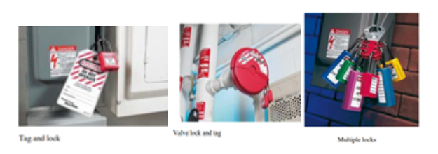
Lockout Isolation devices
To protect workers performing tasks on machinery and equipment, a range of lockout devices is available to secure energy sources and prevent hazards. These devices are designed to physically block energy sources and include options like built-in lock switches, circuit breaker and valve lockouts, chains, and lockout jaws that accommodate multiple padlocks for team use. Safety padlocks are robust and industrial-grade, providing secure lockout across various equipment. Only devices capable of accommodating one or more padlocks or with built-in locks are considered reliable for ensuring equipment remains inactive during maintenance, repair, or cleaning. These tools are essential in preventing accidental activation and safeguarding workers from potentially dangerous energy sources.
One person – one lock: The principle of “one person – one lock” is a key safety rule in lockout/tagout procedures. It ensures that each worker performing maintenance, repair, or cleaning on machinery applies their own lock to the energy isolation device. Each worker is responsible for their own safety by placing their own lock, ensuring that they control when it is safe for the machinery to be reactivated. Since only the worker who placed the lock can remove it, this prevents anyone else from unintentionally starting up the machinery. The presence of multiple locks signals that multiple workers are involved in the task, alerting others that the equipment is still in use and must remain isolated.
One lock – one key: The “one lock – one key” principle is a fundamental safety rule in lockout/tagout procedures. It ensures that each lock used to isolate energy sources has a unique key, enhancing the security of the lockout system. Only the person who placed the lock can unlock it, ensuring that no one else can accidentally or intentionally remove the lock and start the equipment. With a unique key for each lock, there’s no chance of someone using a duplicate or shared key to bypass the lock, thus preventing accidental re-energization of machinery. Each lock is associated with a single worker, clearly identifying who is responsible for that lockout point and who must confirm that work is complete before the lock is removed. By adhering to the “one lock – one key” rule, workplaces create a clear, reliable system that enhances safety for all workers involved in maintenance or repair tasks on machinery and equipment.
Tagout: A tag on its own is not an effective isolation device. A tag acts only as a means of providing information to others at the workplace. A lock should be used as an isolation device, and can be accompanied by a tag.
Arc Flash
An arc flash is a sudden release of electrical energy through the air, typically occurring when a short circuit or fault happens within an electrical system. It produces an intense burst of heat and light, often accompanied by a violent explosion that can cause severe injuries or fatalities.
Arc flashes can reach temperatures as high as 35,000°F (19,427°C), which is hotter than the surface of the sun. This heat can cause severe burns, even from several feet away. The flash produces bright light and a loud noise, which can damage eyesight and hearing. The rapid release of energy creates a pressure wave, similar to a small explosion. This can throw workers, knock over objects, and damage equipment. The blast can propel molten metal, tools, and other debris at high speeds, posing risks of injury from projectiles. Burning materials from the blast can release hazardous fumes that may pose respiratory dangers.
Causes of Arc Flash
Arc flashes can be triggered by various factors, including:
- Equipment failure or degradation
- Dust, corrosion, or moisture buildup
- Dropped tools or accidental contact with energised parts
- Faulty insulation or wiring
Arc Flash Safety
To reduce arc flash risks, workers should follow specific safety measures: Wear specialised arc-rated clothing, helmets, face shields, and gloves. Analyse the potential for arc flash hazards before starting work. Properly isolate equipment and follow lockout/tagout procedures. Regular inspections and maintenance can prevent conditions that lead to arc flashes.
Understanding arc flash risks and implementing safety protocols is essential to protect workers who interact with high-voltage electrical systems.
Interested in our Electrical Engineering Courses?
At iLearn Engineering®, we offer a diverse range of online accredited electrical engineering courses and qualifications to cater to different academic and career goals. Our courses are available in varying credit values and levels, ranging from 40 credit Engineering Diplomas to a 360 credit International Graduate Diploma.
Short Courses (40 Credits)
A selection of our more popular 40 credit electrical diplomas…
Diploma in Electrical and Electronic Engineering
Diploma in Electrical Technology
Diploma in Renewable Energy (Electrical)
First Year of Undergraduate (Level 4 – 120 Credits)
Higher International Certificate in Electrical and Electronic Engineering
First Two Years of Undergraduate (Level 5 – 240 Credits)
Higher International Diploma in Electrical and Electronic Engineering.
Degree equivalent Graduate Diploma (Level 6 – 360 Credits)
International Graduate Diploma in Electrical and Electronic Engineering
All Electrical and Electronic Courses
You can read more about our selection of accredited online Electrical and Electronic Engineering courses here.
Complete Engineering Course Catalogue (all courses)
Alternatively, you can view all our online engineering courses here.
Recent Posts
Civil Engineering Courses and Diplomas: Topics, Skills and Career Routes
Civil Engineering Courses and Diplomas: Topics, Skills and Career Routes Introduction Civil engineering is the backbone of modern society. From roads and bridges to skyscrapers and water systems, civil engineers design, build, and maintain the infrastructure that keeps the world running. If you’re considering a civil engineering course or diploma, understanding what it covers is […]
What Is a Diploma in Engineering? Courses, Levels and Career Routes Explained
What Is a Diploma in Engineering? Courses, Levels and Career Routes Explained Introduction Engineering shapes the world around us, from the buildings we live in to the technology we use every day. But for many aspiring engineers, the biggest question is not whether to pursue engineering, but how to start. Traditional university degrees are not […]
Engineering Courses: How to Choose the Right Route for Your Career
Engineering Courses: How to Choose the Right Route for Your Career Introduction Choosing an engineering course can feel like standing at the beginning of several different roads, each leading towards a different kind of future. One route may lead into mechanical systems and manufacturing. Another may lead towards aircraft, infrastructure, electronics, computing, renewable energy or […]