Transformers: Benefits, Limitations, and Their Role in Electrical Engineering
Introduction
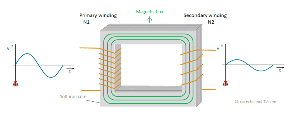
Transformers are one of the most essential devices in the field of electrical engineering, playing a vital role in the generation, transmission, and utilization of electrical energy. At their core, transformers are static machines that transfer electrical power between two or more circuits through the principle of electromagnetic induction, without changing the frequency. Their primary function is to step up (increase) or step down (decrease) voltage levels to ensure efficient power delivery across long distances and safe utilization in homes, industries, and commercial applications.
From the power lines that run across cities to the chargers that power everyday devices, transformers make modern life possible. Understanding how they work, their types, and their applications not only provides insight into the backbone of our electrical systems but also highlights their importance in achieving energy efficiency and reliability.
Advantages of transformers
Transformers offer several key benefits in power systems:
Simple Design and Functionality: Transformers operate based on a straightforward principle of electromagnetic induction between coupled windings, transferring power at the same frequency with minimal losses or distortions.
Voltage and Current Adjustment: Essential in power distribution systems, transformers can step down high transmission voltages or step up currents to meet user requirements.
Isolation and High Efficiency: With galvanic isolation between primary and secondary windings, transformers enhance safety and reliability, with efficiencies reaching up to 97% thanks to advanced materials that reduce hysteresis losses.
Power Transmission and Distribution: Transformers facilitate long-distance, high-efficiency power transmission by stepping up voltage for transmission (power transformers) and stepping it down for industrial, commercial, and residential use (distribution transformers).
Cost Efficiency: Traditional transformers are cost-effective and efficient, offering a low-cost solution for voltage transformation and isolation.
Variety and Versatility: Transformers come in types like distribution, power, current, and isolation transformers, each serving specific applications, such as stepping down current for measurement instruments.
Durability and No Start-up Time: With no moving parts, transformers are long-lasting and require no start-up time, enabling a trouble-free life under normal conditions.
Reversible Connections: Many transformers are reverse connectable, functioning as either step-up or step-down devices, depending on installation.
Multiple Taps: Some transformers offer multiple primary taps for voltage adjustments, allowing them to adapt to variable input voltages and ensure steady operation. These taps are sized for standard voltages (220, 230, 240….etc.), or they can be only slight variations to adjust for consistent over or under voltage at a particular location. These taps are most commonly provided as a percentage of the primary voltage, such as 2-1/2% and 5% (up or down from nominal)
Transformers are integral to modern power systems, enabling efficient, reliable, and flexible power management and distribution.
Disadvantages of transformers
Transformers, despite their benefits, have several drawbacks:
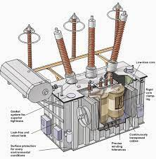
Cooling Requirements: High temperatures shorten the lifespan of insulation materials, so transformers require effective cooling systems (e.g., radiators, fans, oil pumps) to maintain capacity and reliability.
Limited to AC: Transformers only operate with AC, as they block DC signals. This limitation confines their usage in certain applications, such as amplifiers, where they prevent DC voltage interference between stages.
Losses: Though efficient, transformers still experience iron and load losses, especially given their continuous operation in power systems. These losses affect overall energy efficiency.
Outdated Technology: Traditional transformers lack modern features required by smart grids and would benefit from advancements like intelligent transformers.
Size and Weight: Transformers are typically large and heavy, taking up significant space. Reducing their size and weight has been a goal but remains challenging.
Power Quality Issues: Transformers offer limited control over voltage and power quality, requiring additional systems for precise regulation. Voltage dips, sags, and frequency variations in the input are mirrored in the output, affecting stability.
Harmonics: Harmonic distortion from loads, especially in single-phase setups, introduces odd harmonics (e.g., 3rd, 5th, 7th) in the input current, increasing primary winding losses, especially with delta-connected primary transformers.
Maintenance Needs: Transformers can degrade over time due to factors like oil leakage, overloading, unbalanced loading, and harmonic stresses. Effective condition monitoring and maintenance are essential to prolonging their life and preventing failures.
These limitations highlight the importance of innovation and maintenance in transformer technology to meet evolving power system demands and ensure reliable operation.
Transformer operating limitations
Transformers have several operating limitations that prevent them from being entirely efficient or ideal, and while some of these limitations can be minimised, they cannot be entirely eliminated:
1. Transformer Losses (Heat)
2. Temperature Limitations
3. Current Limits
4. Voltage and Frequency Limits
These limitations underscore the need for careful monitoring and management of transformer conditions to optimise performance and durability within practical constraints.
Transformer Losses (Heat)
The thermal rating of a transformer depends on:
1. Heat Produced in the Windings and Connections: Generated by current flowing through the windings, causing copper (I²R) losses.
2. Heat Produced in the Iron Core: Caused by core or iron losses due to hysteresis and eddy currents within the core.
3. Heat Dissipation Efficiency: The transformer’s ability to remove or dissipate heat, reaching thermal equilibrium when heat production equals heat dissipation.
Transformers, especially large ones, operate with high efficiency at full load, but losses are inevitable and are classified as copper losses (I²R losses) and core losses (iron losses).
Copper (or Winding) Losses
Copper losses in a transformer are resistive losses that depend on the load current and are also known as load losses or I²R losses. These losses result from the resistance in the primary and secondary windings and their connections, producing heat as I²R.
At low loads, heat generation is minimal, but as the load increases, heat production rises significantly.
At full load, the windings reach their design temperature, operating at or near their maximum thermal rating.
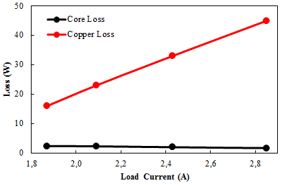
The graph illustrating this shows that heat production increases with load current, demonstrating the proportionality between load current and copper losses in transformer windings.
Iron (or Core) Losses
Iron loss in transformers is caused by eddy currents in the core, which result in energy loss as heat. To reduce this effect, the core is laminated.
Lamination involves stacking thin iron plates with small gaps, which restricts eddy current formation. These laminations disrupt the continuous conductive path, limiting the size and effect of eddy currents. Since magnetic flux flows more easily through iron than through air or oil, laminations guide the flux through the core material, reducing stray flux that could lead to additional core losses.
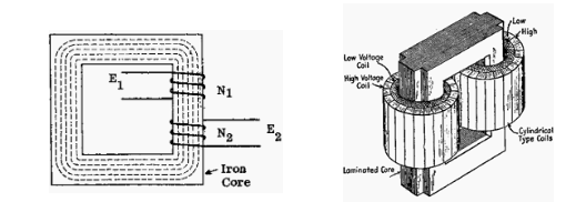
This laminated design minimises unwanted currents and effectively reduces iron loss, increasing transformer efficiency.
Transformer Temperature Limitations
For dry (air-cooled) transformers, typically insulated with silicone resin, a temperature limit of 155°C is imposed. Cooling is achieved by allowing air circulation over the windings and core. With a maximum ambient temperature of 40°C, this results in an allowable temperature rise of 115°C.
For oil-insulated transformers, temperature monitoring includes oil temperature and winding (hot-spot) temperature:
The hot-spot temperature is determined by passing a portion of the load current through a resistor in the oil and measuring the resulting temperature.
Monitoring both oil and hot-spot temperatures is crucial. Insufficient cooling may necessitate a reduction in transformer load to prevent overheating and maintain safe operation.
Current Limits
Current in a transformer has two main effects:
1. Heat Production: current generates heat in the windings due to resistive (I²R) losses.
2. Voltage Drop: Current causes a voltage drop across the output winding, which is proportional to the load current. As the transformer load increases, the secondary voltage decreases due to winding resistance and reactance.
For example, in a transformer with a 5% impedance, the secondary voltage drops by 5% from no load to full load. At half load, the drop would be 2.5%. It’s essential to keep the load within the transformer’s VA rating to avoid excessive voltage drop and overheating.
Voltage and Frequency Limits
Operating voltage and frequency must be kept within rated values in transformers to prevent overheating of the core, a factor sometimes overlooked.
When a transformer operates at its rated voltage and frequency, it maintains a stable, rated flux in the core. If the voltage increases while the frequency stays constant, or the frequency decreases while the voltage remains constant, the core flux rises. This increased flux results in greater hysteresis and eddy current losses, causing the core to overheat.
Careful control of voltage and frequency is therefore essential to avoid excessive heating and ensure efficient transformer operation.
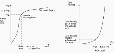
(left) – Typical magnetization curve for a transformer core;
(right) Relationship between core flux and core heating
A 10% voltage increase above a transformer’s rated value will result in a 10% increase in core flux. At this elevated flux level, the iron core begins to saturate. Once saturation occurs, eddy current and hysteresis losses escalate rapidly, generating excess heat.
For this reason, voltage should not exceed the rated value by more than 10%.
Failing to limit voltage can lead to: Core overheating, which may damage the insulation on the laminations, allowing larger eddy currents and even more extreme heating.
Potential core failure due to overheating, which, in severe cases, could lead to melting of the iron laminations and total transformer failure.
Insulation protection rating
The rated insulation levels of Current Transformers (CTs) are based on the CT’s rated voltage and are defined by the power frequency and impulse voltage withstand test voltages specified for the CT.
Up to 11 kV: Dry-type CTs are used, insulated with Epoxy Resin. For 66 kV and above: Paper insulation is used, along with transformer oil for both insulation and cooling.
These insulation methods ensure the CTs can withstand specified test voltages, enhancing durability and performance at different voltage levels.
The following table summarises the different insulation systems available.
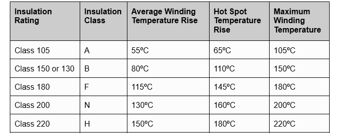
Note: the maximum acceptable temperature rise based on an average ambient of 30ºC during any 24 hour period and a maximum ambient of 40ºC at any time.
Interested in our Electrical Engineering Courses?
At iLearn Engineering®, we offer a diverse range of online accredited electrical engineering courses and qualifications to cater to different academic and career goals. Our courses are available in varying credit values and levels, ranging from 40 credit Engineering Diplomas to a 360 credit International Graduate Diploma.
Short Courses (40 Credits)
A selection of our more popular 40 credit electrical diplomas…
Diploma in Electrical and Electronic Engineering
Diploma in Electrical Technology
Diploma in Renewable Energy (Electrical)
First Year of Undergraduate (Level 4 – 120 Credits)
Higher International Certificate in Electrical and Electronic Engineering
First Two Years of Undergraduate (Level 5 – 240 Credits)
Higher International Diploma in Electrical and Electronic Engineering.
Degree equivalent Graduate Diploma (Level 6 – 360 Credits)
International Graduate Diploma in Electrical and Electronic Engineering
All Electrical and Electronic Courses
You can read more about our selection of accredited online Electrical and Electronic Engineering courses here.
Complete Engineering Course Catalogue (all courses)
Alternatively, you can view all our online engineering courses here.
Recent Posts
Civil Engineering Courses and Diplomas: Topics, Skills and Career Routes
Civil Engineering Courses and Diplomas: Topics, Skills and Career Routes Introduction Civil engineering is the backbone of modern society. From roads and bridges to skyscrapers and water systems, civil engineers design, build, and maintain the infrastructure that keeps the world running. If you’re considering a civil engineering course or diploma, understanding what it covers is […]
What Is a Diploma in Engineering? Courses, Levels and Career Routes Explained
What Is a Diploma in Engineering? Courses, Levels and Career Routes Explained Introduction Engineering shapes the world around us, from the buildings we live in to the technology we use every day. But for many aspiring engineers, the biggest question is not whether to pursue engineering, but how to start. Traditional university degrees are not […]
Engineering Courses: How to Choose the Right Route for Your Career
Engineering Courses: How to Choose the Right Route for Your Career Introduction Choosing an engineering course can feel like standing at the beginning of several different roads, each leading towards a different kind of future. One route may lead into mechanical systems and manufacturing. Another may lead towards aircraft, infrastructure, electronics, computing, renewable energy or […]