Understanding logic gates and truth tables.
In our previous articles, we discussed the binary number system in relation to digital electronics. Now we’ll focus on logic gates and truth tables.
As we mentioned before, binary represents the on-off state. Boolean functions (true or false) can be implemented using electronic gates. There are a couple of points we need to be aware of:
- Electronic gates need a power supply
- Gate inputs are driven by voltages having two nominal values, e.g. 0V and 5V, representing logic 0 and logic 1, respectively.
- The gate output provides two nominal values of voltage only, e.g. 0V and 5V, representing logic 0 and logic 1, respectively. In general, there is only one output to a logic gate, except in some special cases.
- There’s always a time delay between an input being applied and the output responding.
Logic gates
Digital systems are constructed using logic gates. These gates are AND, OR, NOT, NAND, and NOR. We use truth tables to describe their operations.
AND gate
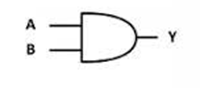
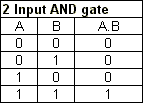
With an AND gate, an electronic circuit gives a high output only if all of the inputs are high. The output can be written as A.B or as AB.
OR gate
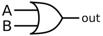
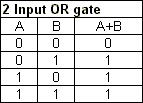
With an OR gate, the electronic circuit gives a high output if one or more of the inputs are high. A plus sign is used to show the OR operation.
NOT gate
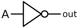

The NOT gate produces an inverted version of the input at its output. It’s also known as an inverter.
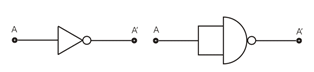
If the input variable is A, the inverted output is known as NOT A. This is also shown as A’, or A with a bar over the top, as shown at the outputs. The diagrams below show two ways that the NAND logic gate can be configured to produce a NOT gate.
It can also be done using NOR logic gates in the same way.
NAND gate
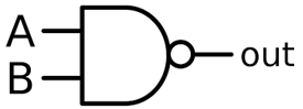
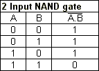
This is a NOT-AND gate which is equal to an AND gate followed by a NOT gate.
The outputs of all NAND gates are high if any of the inputs are low. The symbol is an AND gate with a small circle on the output. The small circle represents inversion.
NOR gate
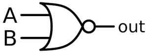
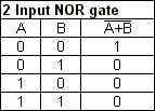
This is a NOT-OR gate which is equal to an OR gate followed by a NOT gate. The outputs of all NOR gates are low if any of the inputs are high.
The symbol is an OR gate with a small circle on the output. The small circle represents inversion. The NAND and NOR gates are called universal functions since with either one the AND and OR functions and NOT can be generated.
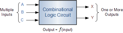
Combinational Logic Circuits
These are memoryless digital logic circuits whose output only depends on the combination of its inputs. The outputs of Combinational Logic Circuits are only determined by the logical function of their current input state, logic “0” or logic “1”, at any given instant in time.
So if one of its input conditions changes state, from 0-1 or 1-0, so too will the resulting output as by default combinational logic circuits have “no memory”, “timing” or “feedback loops” within their design.
Combinational Logic
Combinational Logic Circuits are made up from basic logic NAND, NOR or NOT gates that are “combined” or connected together to produce more complicated switching circuits. These logic gates are the building blocks of combinational logic circuits. An example of a combinational circuit is a decoder, which converts the binary code data present at its input into a number of different output lines, one at a time producing an equivalent decimal code at its output.
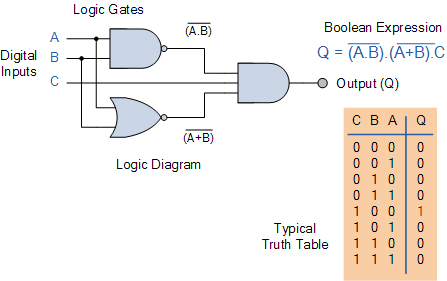
Combinational logic circuits can be very simple or very complicated, and any combinational circuit can be implemented with only NAND and NOR gates, as these are classified as “universal” gates. The three main ways of specifying the function of a combinational logic circuit are:
- Boolean Algebra – This forms the algebraic expression showing the operation of the logic circuit for each input variable either True or False that results in a logic “1” output.
- Truth Table – A truth table defines the function of a logic gate by providing a concise list that shows all the output states in tabular form for each possible combination of input variables that the gate could encounter.
- Logic Diagram – This is a graphical representation of a logic circuit that shows the wiring and connections of each individual logic gate, represented by a specific graphical symbol, that implements the logic circuit.
and all three of these logic circuit representations are shown below.
As combinational logic circuits are made up from individual logic gates only, they can also be considered as “decision making circuits” and combinational logic is about combining logic gates together to process two or more signals in order to produce at least one output signal according to the logical function of each logic gate.
Keep an eye out for our next articles where we dive even further into analogue and digital electronics.
Interested in our courses?
You can read more about our selection of accredited online electrical and electronic engineering courses here.
Check out individual courses pages below:
Diploma in Electrical and Electronic Engineering
Higher International Certificate in Electrical and Electronic Engineering
Diploma in Electrical Technology
Diploma in Renewable Energy (Electrical)
Higher International Diploma in Electrical and Electronic Engineering
Alternatively, you can view all our online engineering courses here.
Recent Posts
Civil Engineering Courses and Diplomas: Topics, Skills and Career Routes
Civil Engineering Courses and Diplomas: Topics, Skills and Career Routes Introduction Civil engineering is the backbone of modern society. From roads and bridges to skyscrapers and water systems, civil engineers design, build, and maintain the infrastructure that keeps the world running. If you’re considering a civil engineering course or diploma, understanding what it covers is […]
What Is a Diploma in Engineering? Courses, Levels and Career Routes Explained
What Is a Diploma in Engineering? Courses, Levels and Career Routes Explained Introduction Engineering shapes the world around us, from the buildings we live in to the technology we use every day. But for many aspiring engineers, the biggest question is not whether to pursue engineering, but how to start. Traditional university degrees are not […]
Engineering Courses: How to Choose the Right Route for Your Career
Engineering Courses: How to Choose the Right Route for Your Career Introduction Choosing an engineering course can feel like standing at the beginning of several different roads, each leading towards a different kind of future. One route may lead into mechanical systems and manufacturing. Another may lead towards aircraft, infrastructure, electronics, computing, renewable energy or […]