

What are logic functions, and how are they applied?
In our previous article, we dived into PLC Programming techniques. In this article, we’re going to check out logic functions and how they are applied to PLC systems.
What is a PLC timer?
A PLC timer is an instruction that controls and operates the device for a specific duration of time. A timer is essential in a PLC for this reason. We can set time-based activity with the help of the PLC programming timer instruction.
The timer instruction provides programming logic and is used to decide when to turn the circuit on or off. It has normally open (NO) and normally closed (NC) contacts.
The image below shows the input and output timers for NO and NC contact in LD programming:
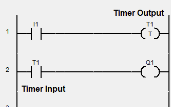
If we want to perform work or device activity in a particular time span, we have to learn I/O timer instructions for writing the PLC program. In the Ladder Diagram (LD) PLC programming, we can set the PLC timer from millisecond (ms) to an hour (hr) time range.
Logic functions used in PLC timer programming
There are several logic functions used in the programming of PLC timers. Let’s have a look at some of them:
AND logic function
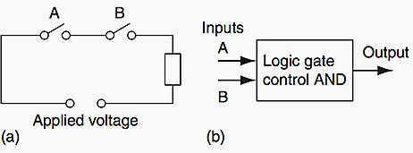
Switch A and switch B have both to be open to give an AND logic situation.
| Inputs | Output | |
| A | B | |
| 0 | 0 | 0 |
| 0 | 1 | 0 |
| 1 | 0 | 0 |
| 1 | 1 | 1 |
The ladder diagram starts with | |, a normally open set of contacts labelled input A, to represent switch A and in series with it | |, another normally open set of contacts labelled input B, to represent switch B. The line then terminates with O to represent the output.
For there to be an output, both input A and input B have to occur, i.e., input A and input B contacts have to be closed
OR logic function
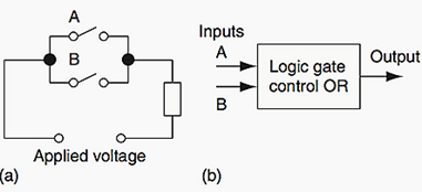
This describes an OR logic gate in that input A or input B must be on for there to be an output.
| Inputs | Output | |
| A | B | |
| 0 | 0 | 0 |
| 0 | 1 | 1 |
| 1 | 0 | 1 |
| 1 | 1 | 1 |
An example of an OR gate control system is a conveyor belt transporting bottled products to packaging, where a deflector plate is activated to deflect bottles into a reject bin if either the weight is not within certain tolerances or there is no cap on the bottle.
NOT logic function
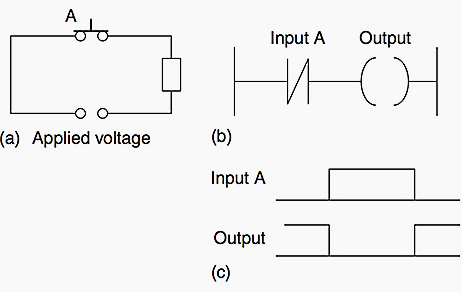
When there is an input to the switch, it opens and there is then no current in the circuit. This illustrates a NOT gate in that there is an output when there is no input and no output when there is an input. The gate is sometimes referred to as an inverter.
| Input A | Output |
| 0 | 1 |
| 1 | 0 |
With no input-to-input A, the contacts are closed and so there is an output. When there is an input-to-input A, it opens and there is then no output. An example of a NOT gate control system is a light that comes on when it becomes dark, i.e., when there is no light input to the light sensor there is an output.
NAND logic function
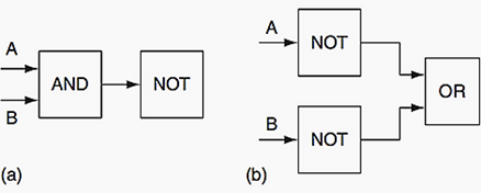
Suppose we follow an AND gate with a NOT gate. The NOT gate will invert all the outputs from the AND gate. An alternative, which gives exactly the same results, is to put a NOT gate on each input and then follow that with OR
| Inputs | Output | |
| A | B | |
| 0 | 0 | 1 |
| 0 | 1 | 1 |
| 1 | 0 | 1 |
| 1 | 1 | 0 |
Bthe inputs A and B have to be 0 for there to be a 1 output. There is an output when input A and input B are not 1. The combination of these gates is termed a NAND gate.
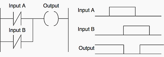
An example of a NAND gate control system is a warning light that comes on if, with a machine tool, the safety guard switch has not been activated and the limit switch signalling the presence of the workpiece has not been activated.
NOR logic function
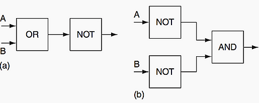
Suppose we follow an OR gate by a NOT gate. The NOT gate will to invert the outputs of the OR gate. An alternative, which gives exactly the same results, is to put a NOT gate on each input and then an AND gate for the resulting inverted inputs.
| Inputs | Output | |
| A | B | |
| 0 | 0 | 1 |
| 0 | 1 | 0 |
| 1 | 0 | 0 |
| 1 | 1 | 0 |
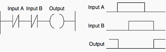
The combination of OR and NOT gates is termed a NOR gate. There is an output when neither input A or input B is 1.
Keep an eye out for our next articles where we’re going to dive even further into Programmable Logic Controller systems and their uses.
Interested in our courses?
You can read more about our selection of accredited online electrical and electronic engineering courses here.
Check out individual courses pages below:
Diploma in Electrical and Electronic Engineering
Higher International Certificate in Electrical and Electronic Engineering
Diploma in Electrical Technology
Diploma in Renewable Energy (Electrical)
Higher International Diploma in Electrical and Electronic Engineering
Alternatively, you can view all our online engineering courses here.
Recent Posts
Civil Engineering Courses and Diplomas: Topics, Skills and Career Routes
Civil Engineering Courses and Diplomas: Topics, Skills and Career Routes Introduction Civil engineering is the backbone of modern society. From roads and bridges to skyscrapers and water systems, civil engineers design, build, and maintain the infrastructure that keeps the world running. If you’re considering a civil engineering course or diploma, understanding what it covers is […]
What Is a Diploma in Engineering? Courses, Levels and Career Routes Explained
What Is a Diploma in Engineering? Courses, Levels and Career Routes Explained Introduction Engineering shapes the world around us, from the buildings we live in to the technology we use every day. But for many aspiring engineers, the biggest question is not whether to pursue engineering, but how to start. Traditional university degrees are not […]
Engineering Courses: How to Choose the Right Route for Your Career
Engineering Courses: How to Choose the Right Route for Your Career Introduction Choosing an engineering course can feel like standing at the beginning of several different roads, each leading towards a different kind of future. One route may lead into mechanical systems and manufacturing. Another may lead towards aircraft, infrastructure, electronics, computing, renewable energy or […]