

What are the principles of inductance and capacitance?
In our previous article on inductance, we jumped into the behaviour of inductance and what it is. Now we’re going to look at the principles of inductance, as well as the principles of capacitance.
Inductance and Capacitance.
We’ve already touched on the surface of inductance in our previous article, now let’s find out even more. The behaviour of the inductor is based on the properties of the magnetic field generated in a coil of wire. We need to know the following two laws when we look at inductance:
- Ampere’s Law: current in a coil ⇒ magnetic field.
- Faraday’s Law: time-varying magnetic field ⇒ induced voltage (emf).
The time-varying magnetic field is produced by a changing current, and the behaviour of the capacitor is based on the properties of the electrical field created in a non-conductor that is placed between two conductors. In other words, the capacitor is a non-conductor sandwiched between two conductors.
Energy isn’t generated by an inductor or capacitor but is stored in them. This means they are passive devices. The inductor stores energy in it’s magnetic field, and the capacitor stores energy in its electric field.
Energy stored in an inductor
The energy stored, W, in the magnetic field of an inductor is given by:

If we look at an example to fully understand it, let’s imagine an 8-H inductor has a current of 3A flowing through it. We can calculate the energy stored in the energy field of the inductor by:

The capacitor
Capacitors are short-term ‘charge-stores’, similar to batteries. While a battery produces e-s, capacitors just stores them. It consists of two metal plates separated by a layer of insulating material called a dielectric.
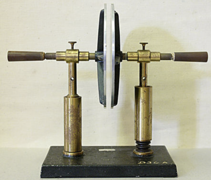
There are two types of capacitors:
- Electrolytic capacitors: these hold much more charge and have to be connected with the correct polarity, or they can explode.
- Non-electrolytic: these hold less charge and can be connected either way around in a circuit.
How does a capacitor work?
When two conducting plates are connected to a battery, electrons move towards one plate. The positive plate loses electrons, and eventually both plates are left with equal and opposite charge. When a capacitor is charged, i.e when the electrons are no longer moving, the capacitor is said to have charge Q.

The working voltage is equal to the maximum potential difference that can be applied, and above this, the insulation of the dielectric breaks down.
Capacitance, C, is “the charge, Q, required to cause unit potential difference, V, in a conductor. It’s measured in Farads (normally mF or μF)”. 1 Farad is the capacitance of a conductor, which has potential difference of 1 volt when it carries a charge of 1 coulomb.
Charging a capacitor using D.C
At any time, t, after the switch is closed, the charge, Q, on the capacitor can be calculated using Q=It.

The variable resistor can be altered to keep the current constant, which is not easy! When the current is constant, then we would calculate the charge and take a reading of the p.d. If we plot a graph of capacitance against voltage, it looks like this:

The gradient of the graph will equal the capacitance of that capacitor.
Charge stored in a Capacitor
Electrical potential energy is stored when a capacitor is charged. The energy stored is equal to the work done to force extra charge Δq (i.e. from q to q+Δq) onto the plates and is given by ΔE=vΔq, where v is the plate potential difference.
The area under the graph is equal to the energy stored = (½bh)
We can combine previous equations to give the following:
Let’s look at an example to see how it all works. Imagine a heart defibrillator that delivers 4.00 x 10² J of energy by discharging a capacitor initially at 1.00 x 10⁴ V. We want to figure out what it’s capacitance is.
We are given Ecap and V, and need to find C, the capacitance. Of the three equations we could use, the most convenient one is

So, when we solve this expression for C and enter the values we’re given, we get

This is a fairly large, but manageable, capacitance at 1.00 × 10⁴ V.
Interested in our courses?
You can read more about our selection of accredited online electrical and electronic engineering courses here.
Check out individual courses pages below:
Diploma in Electrical and Electronic Engineering
Higher International Certificate in Electrical and Electronic Engineering
Diploma in Electrical Technology
Diploma in Renewable Energy (Electrical)
Higher International Diploma in Electrical and Electronic Engineering
Alternatively, you can view all our online engineering courses here.
Recent Posts
Types of Aircraft Drag Explained: Induced, Profile and Interference Drag
Types of Aircraft Drag Explained: Induced, Profile and Interference Drag An aircraft experiences several forms of aerodynamic drag at the same time. Some result from generating lift, some arise as air flows over the aircraft’s surfaces, and others are created when airflow around neighbouring components interacts. For a conventional aircraft in subsonic flight, total drag […]
Induced Drag Explained: Why Flying Slower Can Increase Drag
Induced Drag Explained: Why Flying Slower Can Increase Drag Why can an aircraft experience more drag when it flies more slowly? We usually associate greater speed with greater air resistance, but a wing must also generate enough lift to support the aircraft. Induced drag is the drag associated with producing lift on a finite-span wing. […]
Laminar vs Turbulent Boundary Layers: Why Airflow Separates from Aircraft Wings
Laminar vs Turbulent Boundary Layers: Why Airflow Separates from Aircraft Wings Airflow around an aircraft wing is often shown as smooth streamlines passing neatly over the aerofoil. In reality, the thin layer of air immediately next to the wing surface behaves very differently from the undisturbed airflow further away. This region is called the boundary […]