How to Describe and Analyse Undamped Vibrations?
In vibration analysis we could say that we are interested in one of two approaches, either:
- to control undesirable vibration, e.g. loosening of bolts, fatigue, human discomfort
- to enhance desirable vibration, e.g. mechanical sieves / agitators, ‘shakers
If we are two investigate either of these points then we need to consider what the cause of vibration is. We can say that any disturbance on a mechanical system which is in a state of equilibrium will result in a vibration response. More specifically, that disturbance will result in an interchange of kinetic and potential energy between the ‘masses’ and the ‘springs’ of the system. Examples of disturbance include: wind gusts on aircraft/automobiles/bridges, periodic impulses from firing events in an internal combustion engine etc
Basic Concepts
Consider a typical motor vehicle which has four wheels, one at each corner and incorporated within each corner is a suspension system. We can model such a system as shown below:
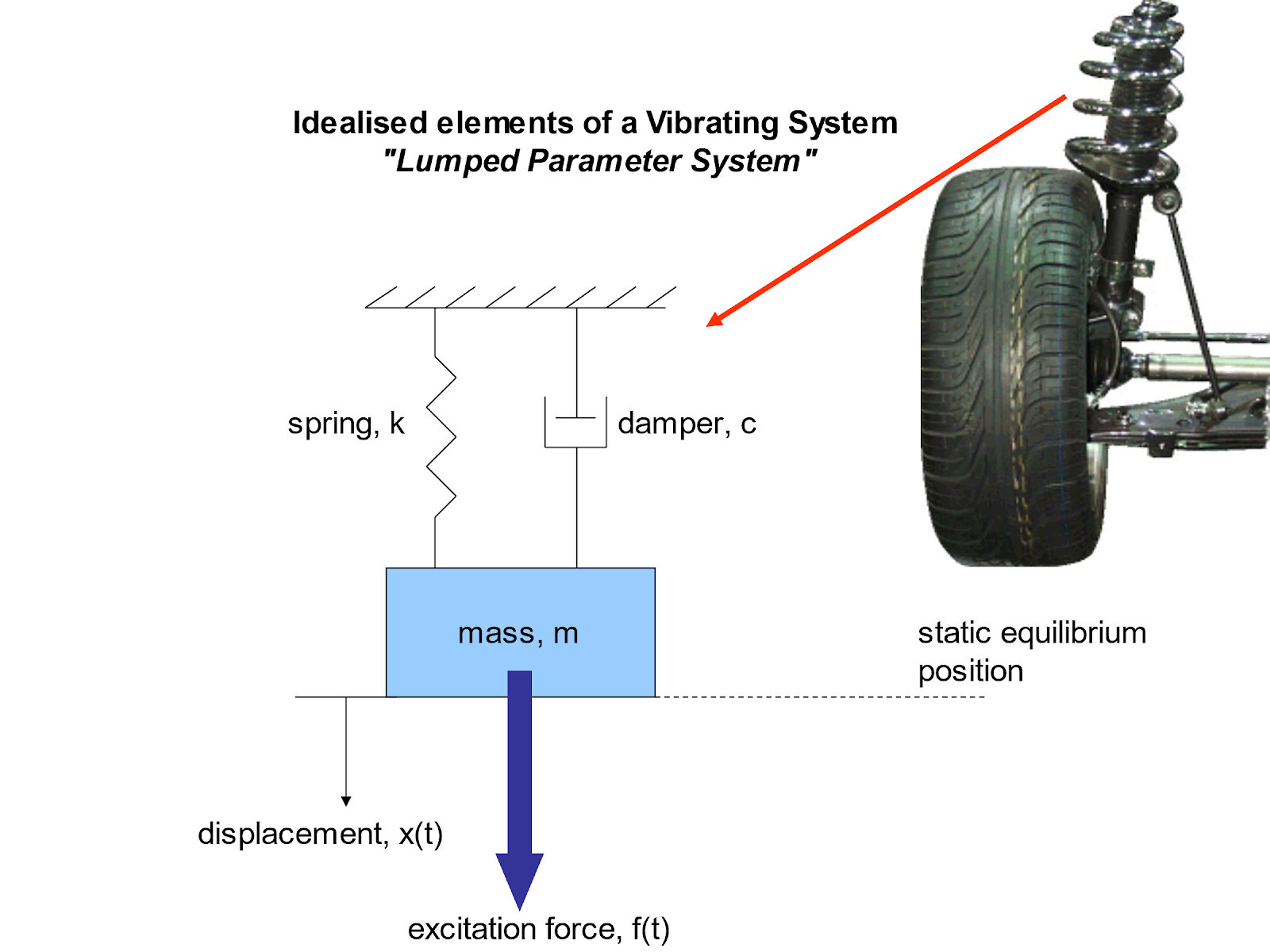
We have modelled the vehicle suspension system as an idealised lumped parameter system. Such a model has essentially ‘lumped’ all of the mass, stiffness and damping of the real structure into idealised lumped parameters.
The lumped parameter system comprises:
Mass (kg): this is where the inertia of the real structure is represented and modelled. The idealised mass has the following features:
- rigid body where work done is stored as kinetic energy – this is where all of the mass of the real suspension system is modelled.
Spring (N/m): this is where the stiffness of the real structure is represented and modelled. The idealised spring has the following features:
- no mass
- elastic component of the structure is modelled here
- linear spring obeys Hooke’s Law
- spring constant = stiffness = k = force / unit deflection
- however, non-linear springs do exist
- work done stored as potential (or spring) energy
Damper (Ns/m): this is where the damping of the real structure is represented and modelled. The idealised damper has the following features:
- no mass, no elasticity
- viscous damping force proportional to velocity
- viscous damping coefficient, c = force / unit velocity
- however, non-linear damping does exist
- work done / energy dissipated as heat (non-conservative system)
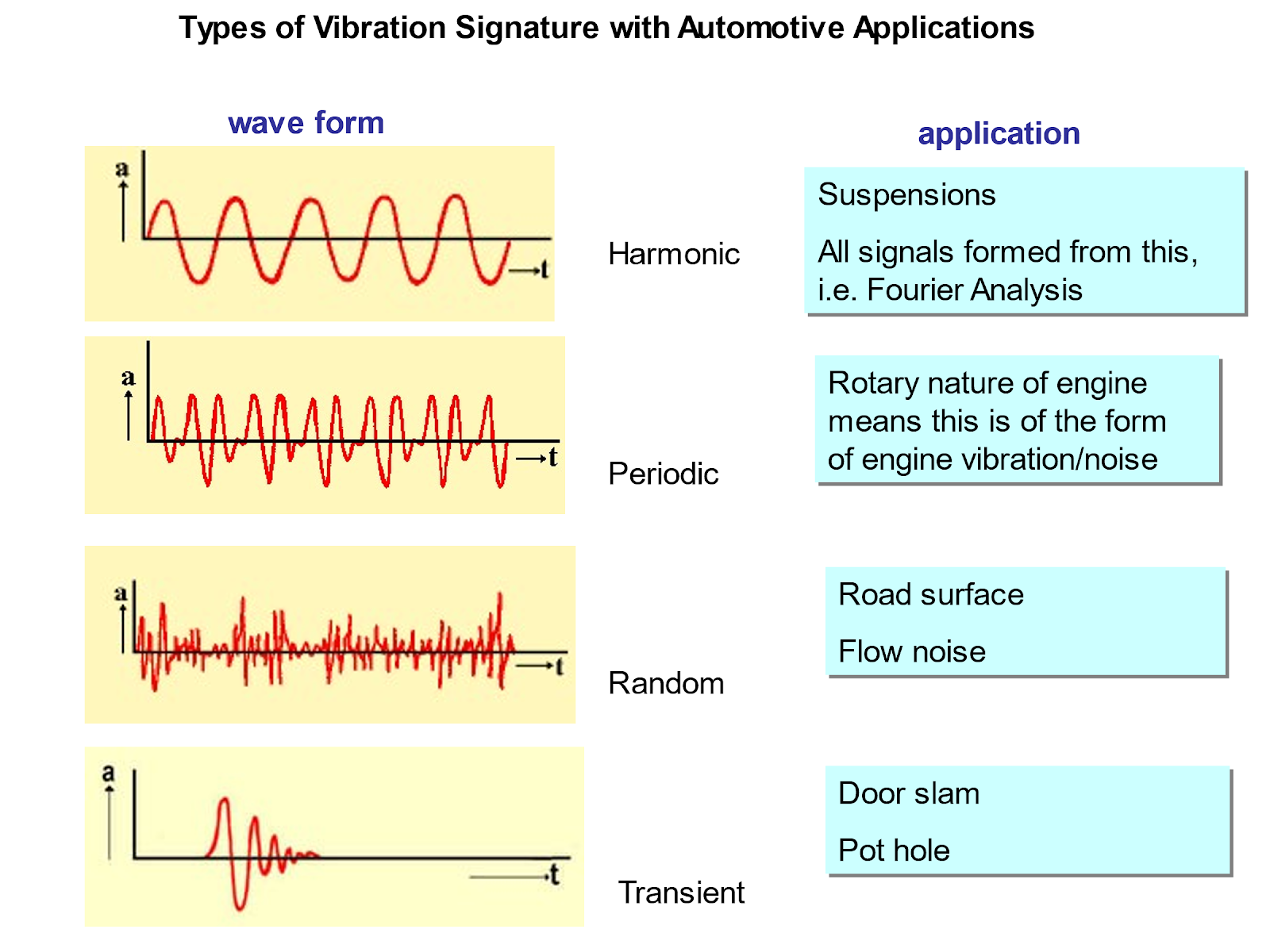
A simple sinusoidal or harmonic signal might be formed from analysis of a suspension system for instance. A periodic signal is one which repeats itself indefinitely, and whilst the harmonic signal is itself periodic, so too are more complex signals such as those due to the vibration response of a reciprocating internal combustion engine.
In contrast to periodic signals which have a repeating pattern, random signals have no predictable element to them and so statistical measures such as mean and standard deviation might be employed to describe such a signal. Random vibration signals are produced from road noise and vibration as the surface profile of a road is random in nature. The aerodynamic noise of the wind past a vehicle will also be random in nature.
A transient signal is one in which it is time dependent and typically short in duration, e.g. the vibration response signal resulting from closing a door or driving over a pothole in the road!
Effect of frequency on response
Below we observe three masses on springs, where the black mass has the lowest frequency and the blue the greatest frequency of vibration. Notice how the higher the frequency the lower the time period shown on the time trace on the right. There is no damping in this model.
Undamped
Below we observe two masses on springs, where the black mass has zero damping and the blue has damping added. Notice how the blue mass has a time response that decays with time.
Damped
Degrees of Freedom (DOF)
A degree of freedom is an independent parameter that defines the state of a mechanical system. In vibrating systems, it usually refers to an independent displacement (translation or rotation) that can occur without violating any constraints.
- 1-DOF system: Can move in one independent direction (e.g. vertical displacement only).
- 2-DOF system: Two independent motions, often coupled.
- n-DOF system: Has n independent displacements that can occur simultaneously.
Examples of DOF in Vibrating Systems
1. Single Degree of Freedom (SDOF) System
- Example: Mass-spring-damper system.
- Motion: Vertical displacement of the mass.
- Equation of motion:
m +c +kx =F(t) - where: m: mass, c: damping coefficient, k: spring stiffness, x: displacement, F(t): external force
Two Degrees of Freedom (2DOF) System
- Example: Two masses connected by springs.
- Motion: Displacement of each mass.
- Leads to coupled differential equations, where the motion of one mass affects the other.
3. Multi-Degree of Freedom (MDOF) Systems
- Example: Multi-story buildings, mechanical linkages, complex machinery.
- Each mass or joint contributes one or more degrees of freedom.
Determining DOF
To determine the degrees of freedom of a vibrating system:
- Identify all the independent masses.
- Count the number of independent displacements or rotations possible for each mass.
- Apply constraints (fixed supports, joints) to eliminate dependent motions.
Effective Stiffness of Multiple Springs
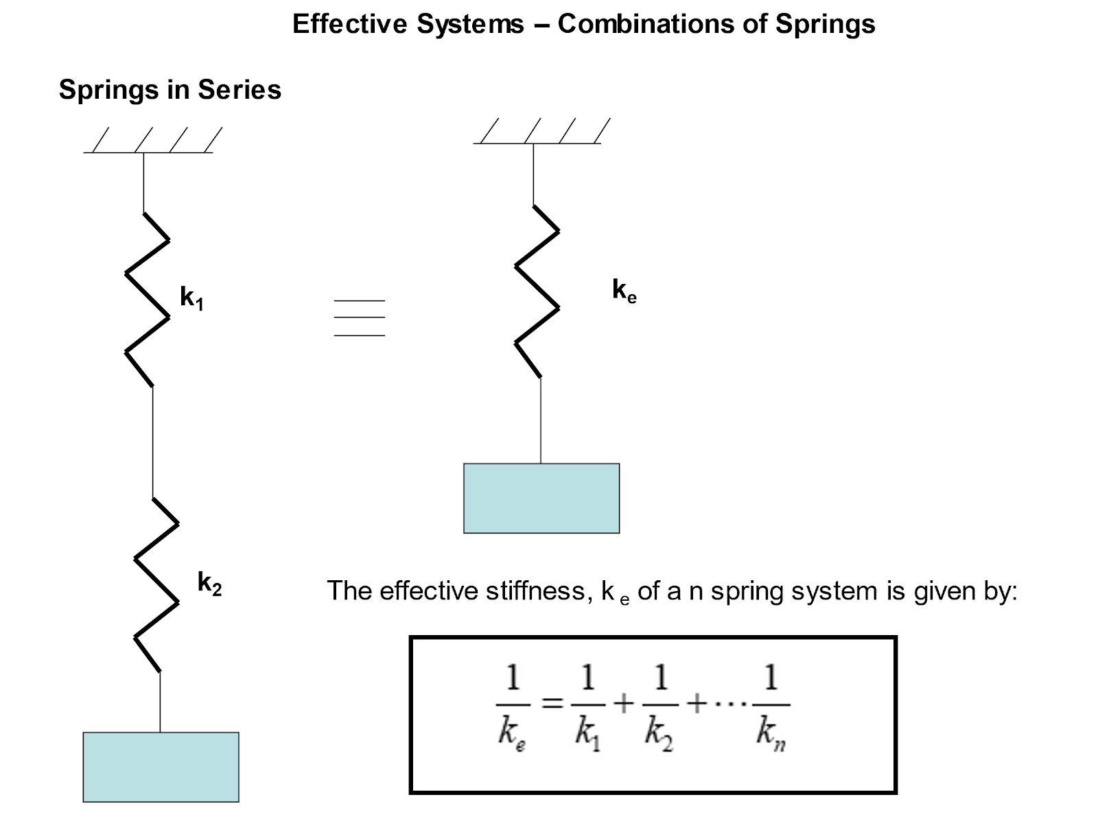
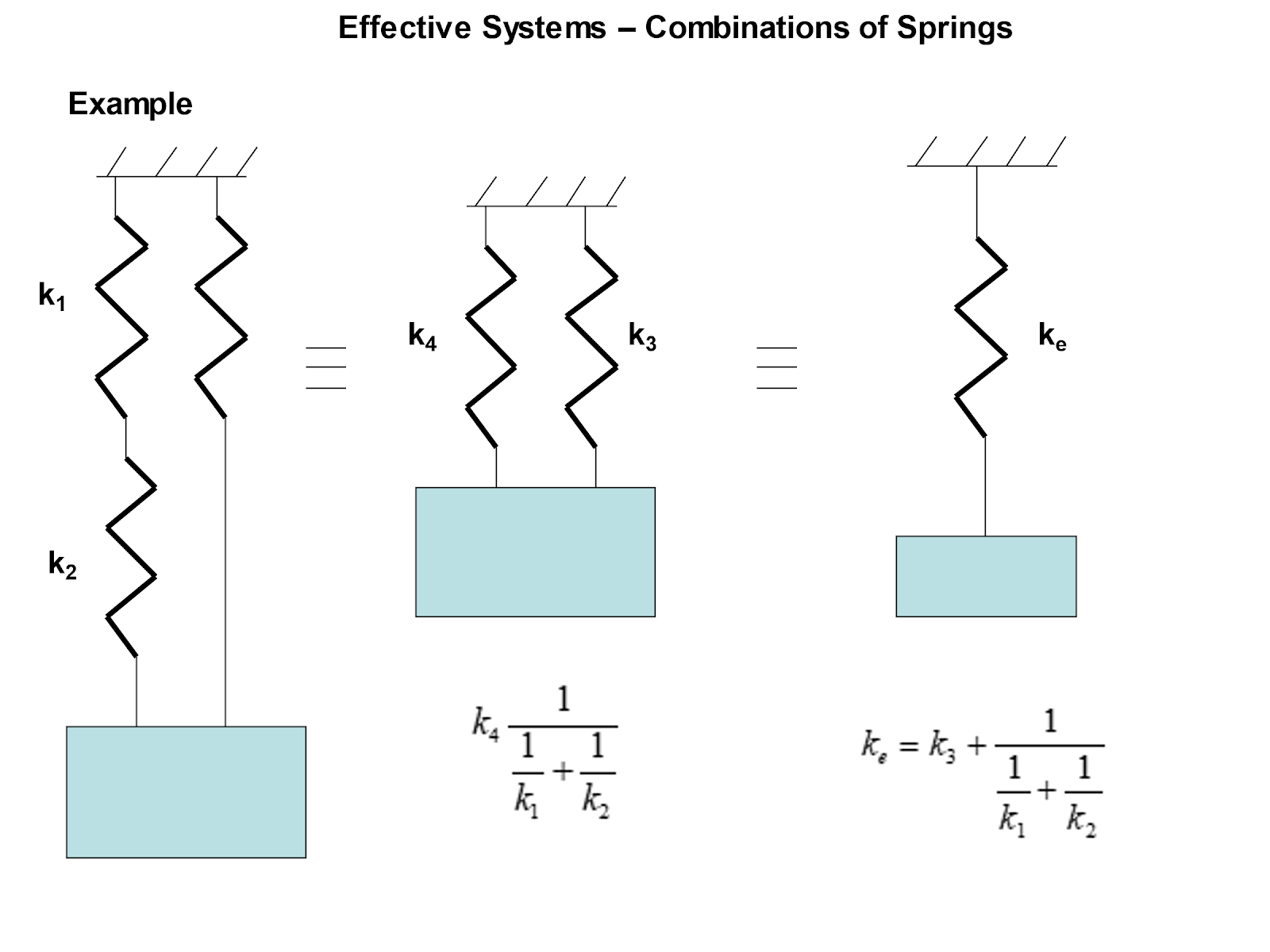
Let us now consider the analysis of systems with multiple spring elements. We can often combine several spring elements into a single so-called ‘effective’ stiffness, ke.
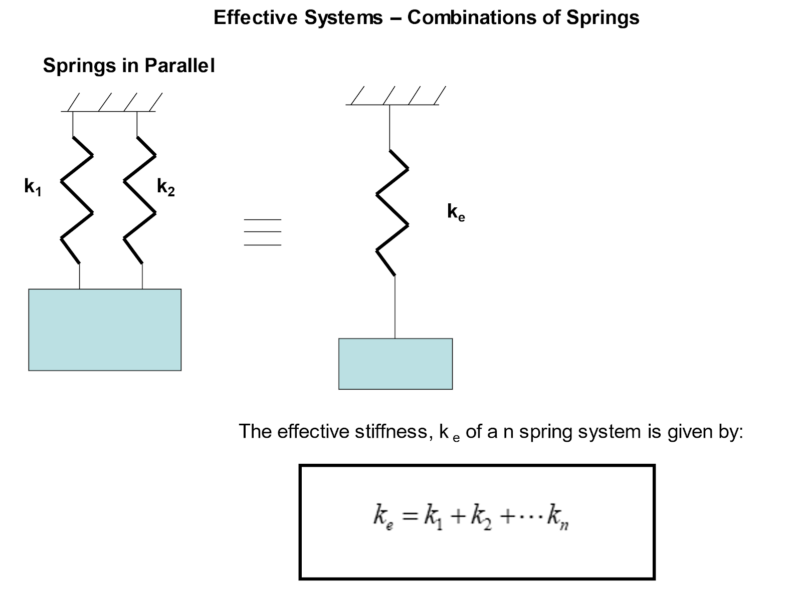
There are two cases to consider: springs in series and springs in parallel.
Example 1:
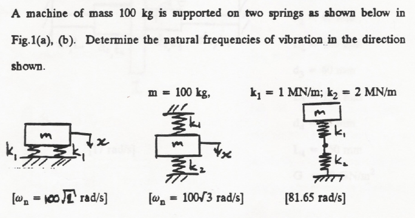
(a)The springs are in parallel so:
ke = k1 + k2 + …kn
ke = 1 x 10⁶ + 1 x 106 = 2 x 106 = 2MN/m
ωn = √ke / m
ωn = √2 x 10⁶ / 100 = 100√2 = 141.4 rad / s
(b) be careful – the springs may look like they are in series, but they are not!
Both springs have one end attached to the mass and their other end attached to earth (where earth is common). Therefore, the springs are in parallel.
ke = k1 + k2 + …kn
ke = 1 x 10⁶ + 2 x 106 = 3 x 106 = 3MN/m
ωn = √ke / m
ωn = √3 x 10⁶ / 100 = 100√3 = 173.2 rad / s
(c) The springs are in series.
1/ke = 1/k1 + 1/k2 + …1/kn
1/ke = 1 / 1 x 10⁶ + 1 / 2 x106 = 1.5 x 10⁻⁶
ke = 1 / 1.5 x 10-6 = 666.67 x 10³ N/m
ωn = √ke / m
ωn = √666.67 x 10³ / 100 = 81.6 rad/s
Example 2:
A simple undamped lumped parameter single degree of freedom (SDOF) system has a mass of 10 kg. When the spring is subject to a force of 1 kN it stretches by 50 mm. Calculate the natural frequency of vibration in rad/s and Hz.
First of all, we need to determine the stiffness of the spring from the force displacement information:
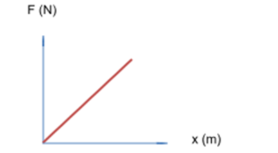
The stiffness, k, of a spring can be found from the gradient of the force – displacement graph, which is given by:
k = F/x = 1000/ 50×10-3 = 20×103 N/m
Now we can find the natural frequency:
ωn = √ke / m
ωn = √20 x 103 / 10 = 44.7 rad/s
To convert to Hz:
ω = 2πf
where f is the frequency in Hz. Therefore:
F = ω / 2π = 44.7 / 2π = 7.1 Hz
Interested in our engineering courses?
We have over 70 courses across all major engineering disciplines, including, mechanical, electrical and electronic, civil, aerospace, industrial, computer and general engineering. Visit our course catalogue for a complete list of fully accredited engineering programmes.
A small selection of short courses …
Diploma in Mechanical Engineering
Diploma in Structural Engineering
Level 6 Courses
International Graduate Diploma in Mechanical Engineering
International Graduate Diploma in Civil Engineering
International Graduate Diploma in Aerospace Engineering
Level 5 Courses
Higher International Diploma in Mechanical Engineering
Higher International Diploma in Civil Engineering
Higher International Diploma in Aerospace Engineering
Level 4 Courses
Higher International Certificate in Mechanical Engineering
Higher International Certificate in Civil Engineering
Higher International Certificate in Aerospace Engineering
Alternatively, you can view all our online engineering courses here.
<
Recent Posts
Civil Engineering Courses and Diplomas: Topics, Skills and Career Routes
Civil Engineering Courses and Diplomas: Topics, Skills and Career Routes Introduction Civil engineering is the backbone of modern society. From roads and bridges to skyscrapers and water systems, civil engineers design, build, and maintain the infrastructure that keeps the world running. If you’re considering a civil engineering course or diploma, understanding what it covers is […]
What Is a Diploma in Engineering? Courses, Levels and Career Routes Explained
What Is a Diploma in Engineering? Courses, Levels and Career Routes Explained Introduction Engineering shapes the world around us, from the buildings we live in to the technology we use every day. But for many aspiring engineers, the biggest question is not whether to pursue engineering, but how to start. Traditional university degrees are not […]
Engineering Courses: How to Choose the Right Route for Your Career
Engineering Courses: How to Choose the Right Route for Your Career Introduction Choosing an engineering course can feel like standing at the beginning of several different roads, each leading towards a different kind of future. One route may lead into mechanical systems and manufacturing. Another may lead towards aircraft, infrastructure, electronics, computing, renewable energy or […]