Unpacking the Machining Response of Composite Materials
Introduction
In modern manufacturing, composite materials—notably carbon and glass fibre reinforced polymers—are valued for their lightweight strength and design flexibility. Yet machining these advanced materials reveals unique challenges that set them apart from traditional metals. Unlike homogeneous alloys, composites are heterogeneous, combining hard, abrasive fibres with softer matrix materials. This makes processes like drilling, milling, routing, and turning prone to defects such as delamination, surface fuzz, fibre pull-out, and excessive tool wear.
The blog beautifully “unpacks” how these issues arise: fibre orientation can alter cutting forces dramatically, while the elastic rebound of fibres (known as “bouncing-back”) influences depth-of-cut accuracy—and ultimately, the integrity of the machined part. It also explores how curing conditions, feed rates, rake angles, and tool geometry all play pivotal roles in machining performance.
As we look deeper, the interplay between tool design and composite structure becomes the linchpin of productivity. Understanding these interactions isn’t just academic—it’s what determines whether a composite component meets stringent aerospace or automotive standards for dimensional precision, surface integrity, and durability.
Ceramics, metals, and polymers are the most typical representations of the field of materials.
The physical and mechanical characteristics of various materials vary, which has an impact on the machining process.
When machining, there are several characteristics to take into account, including cutting speed, feed rate, and depth of cut, which are all influenced by the material of the workpiece, the type of tooling used, and the machine’s size. Where cutting speed is the rate at which the workpiece material is sliced by the cutting tool. Surface feet per minute are used to measure it. Cutting feed describes the rate at which the workpiece moves in the direction of the cutting tool. Inches per minute are used to measure it. As such, these characteristics are unique when using different types of materials.
Attributes of composite material
Due to their superior fatigue and creep resistance as compared to metallic materials, high strength-to-weight ratio, high specific stiffness, and ability to reduce weight in the completed components, composite materials are continuously replacing traditional engineering materials in many applications. When reinforcement and matrix materials are combined, a composite material is created that has superior qualities than the sum of its parts. Each substance keeps its own chemical, physical, and mechanical qualities, in contrast to regularly used metallic substances and alloys.
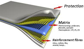
The matrix phase of composite materials is typically one phase and can be made of plastic, metal, or ceramic. Glass, graphite, boron, aramids, and a variety of other oxides, carbides, and nitrides can all be used as the reinforcing phase. The matrix phase typically has a higher degree of ductility and a lower degree of hardness, whereas the reinforcing phase typically has a higher degree of stiffness and strength than the matrix phase. Chemical, thermal, and electrical properties are added as a result of reinforcement. A hybrid composite is one that contains more than one type of fibre in a matrix.
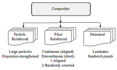
The reinforcing phase may consist of fibres or particles in fibre-reinforced composites, glass fibre-reinforced plastic (GFRP), or carbon fibre-reinforced plastic (CFRP). Wind energy systems, machine tools, sporting items (golf clubs, tennis rackets, bicycles, arrows, surfing, and skateboards), and biomedical products all make extensive use of composite materials.
The most common type of composite material utilised in both commercial and military aircraft systems is fibre-reinforced polymer composites (FRP), notably those using carbon fibre.
Machining characteristics with composite material
To reduce the amount of machining necessary for manufactured items, composites are created in close to-net shape. To cut composite parts with the requisite accuracy and surface quality, turning, milling, or grinding processes are utilised. The assembly of parts in intricate aeroplane constructions is made possible by drilling operations and edge trimming to the final shape.
There is a demand for stronger and more durable cutting tools because of the durability and abrasiveness of composite materials. In this regard, a lot of the knowledge on machining that is applicable to different high-speed steel and carbide cutting tool materials used for machining metals, as well as some thermoplastics, cannot be applied to machining composites. The mechanisms involved in cutting composite materials have been considered to be significantly different from those seen when cutting homogeneous materials. Composite materials have unique features that affect how they behave during machining.
As a result of the fact that composites are neither homogeneous nor isotropic, the machining characteristics rely on the tool path in relation to the direction of the reinforcing fibres.
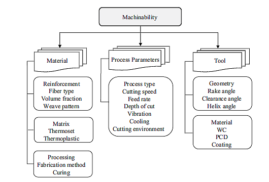
One or more of the following factors can be used to explain the machinability of composite materials:
- Surface roughness
- surface integrity (delamination and HAZ)
- cutting forces and power
- susceptibility to generate built-up edge
- chip formation:
- tool wear and life
The behaviour of the material during cutting cannot be predicted using the qualities of a single component alone. Important considerations include the uniformity of the reinforcement distribution, the alignment of the reinforcement in one direction, and the matrix’s crystalline structure. The quality of the machined surface and cutting tool wear are both influenced by the interaction between the matrix strength at the interface.
However, in general, machining composites causes the following types of damage: burrs, debonding, intralaminar cracks, delamination, and heat damage. Selected process parameters have a significant impact on how many of these flaws there are. After machining, attention should also be given to the circularity of the holes.
Chip Formation
The nature of the reinforcement and the angles of the cutting tool determine the sort of chip that is produced while machining composite materials.
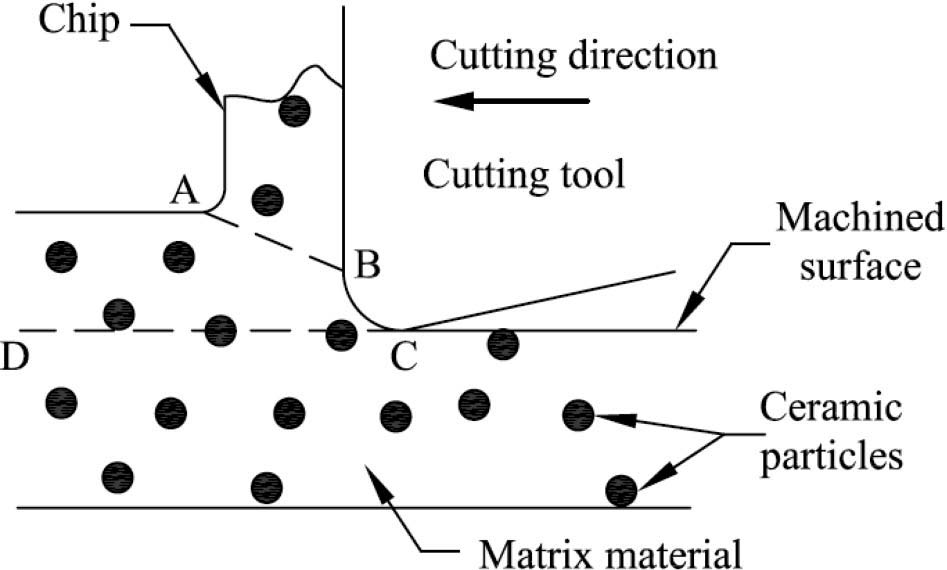
Cutting process in particulate-reinforced composites
The mechanism of chip production is caused by the shearing force along the shear plane AB, much like when a monolithic material is machined orthogonally with a sharp-edged tool. The material deformation and particle displacement caused along BC by the tool edge radius are what cause the ploughing force (plastic zone without a chip). Along the CD line, there is a particle fracture.
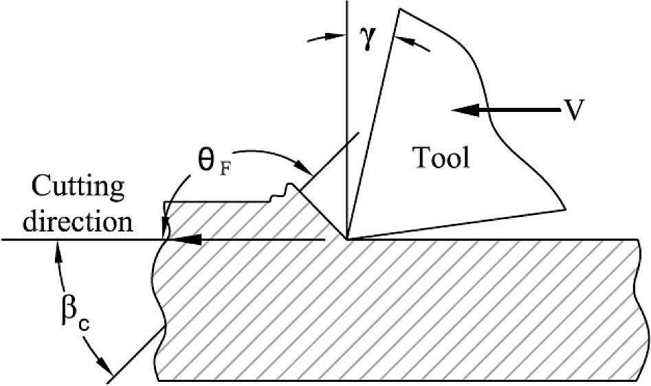
Unidirectional composites cutting
The fibre orientation angle F in relation to the cutting speed (V) direction determines the mode of chip production in unidirectional FRPs The diagram below shows that this angle is measured counterclockwise with respect to the cutting direction. Greater than 90° unidirectional fibre orientations are often classed as negative orientations.
Multidirectional composites cutting
Each ply in the multidirectional structure behaves independently of the nearby plies during orthogonal cutting of multidirectional composites. By adding the cutting forces for each unidirectional ply in the laminate, the cutting forces may be calculated. Additionally, the individual plies’ cut surface properties closely approach those attained from unidirectional machining of the individual plies. When cutting significant orientation angles, the surrounding plies provide support against probable out-of-plane distortion.
Composite machining with non traditional technique
Since FRP structures are created to be nearly net-shaped, machining by edge trimming, sawing, drilling, grinding, or milling must still be done. The inhomogeneity of their material qualities makes it challenging to machine them using traditional techniques. Material degradation from conventional machining includes delamination, fibre pullout, and insufficient surface roughness of the cut.
When milling FRP laminates utilising the majority of traditional machining techniques, delamination still poses a significant issue. Due to the carbon fibres’ abrasive nature, tool wear is another issue. Additionally, the addition of coolant harms the composite material over the long run in other ways. Nontraditional machining techniques including abrasive water jet machining, laser beam machining , and electro discharge machining are used to circumvent the challenges posed by conventional cutting of composites.
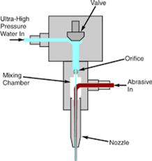
Abrasive water jet machining (AWJM)
High speed water jet with abrasive particles is used by AWJM. Erosion happens as the jet impacts the workpiece, cutting the composite material. Due to its inherent benefits, such as its absence of heat damage, lack of tool wear, modest cutting forces, high flexibility, less material wastage, and higher productivity, AWJM is a good option for milling composite materials.
When abrasives are added to the water jet, it becomes possible to use AWJM to cut through brittle materials including ceramic, glass, and composites that break and shatter when struck. For brittle materials, the maximum erosion happens at an impact angle of about 90°, but for ductile materials, the peak erosion angle is between 20° and 30°.
Water pressure, stand-off distance, feed rate, and abrasive concentration are some of the process variables. A variety of machining processes, including pocket milling, turning, drilling, and plain cutting, use AWJM.
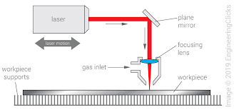
Laser beam machining (LBM)
The use of lasers as a substitute for noncontact machining techniques has a number of benefits, including simplicity of automation, the absence of cutting force, and the absence of the need of liquid or abrasive media. Different fibre orientations are laminated and bonded together in a polymer matrix to create Fibre reinforced polymer (FRP) composites. Due to the significant variances in material properties between the two constituents at high temperatures, each constituent retains its unique thermal characteristics and presents a problem in laser processing.
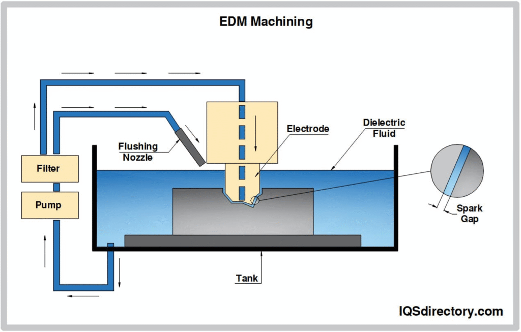
Electro Discharge machining (EDM)
FRP by EDM composites are challenging to machine because they are constructed of homogenous materials that include electrically conductive high tensile fibres and an electrically non-conductive matrix material, which is often made of plastic or epoxy resin.
Defects in composites machining
Many elements, including the acquisition process, machining, mechanical stress, environmental conditions, etc., cause composite flaws in the material structure.
1. Delamination: Refers to instances where a laminate fails because of insufficient adhesion on a plane between neighbouring layers. It is the most typical type of damage or flaw for laminated composites. It happens when the matrix’s toughness and strength are comparatively poor.
2. Cracking: During drilling, milling, and trimming, cracking is a typical type of damage to composite materials. Impact damage, linking, crazing, delamination, and crack propagation processes including fatigue are all causes of cracking.
3. Fibre waviness: The in-plane kinking of a ply’s fibres, which has a significant impact on laminate strength. In high integrity aerospace and defence components, it is especially concerning.
4. Heat impacted zone: The area of the matrix that has been thermally damaged as a result of the heat produced during normal operations.
Interested in our engineering courses?
We have over 70 courses across all major engineering disciplines, including, mechanical, electrical and electronic, civil, aerospace, industrial, computer and general engineering. Visit our course catalogue for a complete list of fully accredited engineering programmes.
A small selection of short courses …
Level 6 Courses
International Graduate Diploma in Mechanical Engineering
Level 5 Courses
Higher International Diploma in Industrial Engineering
Higher International Diploma in Mechanical Engineering
Level 4 Courses
Higher International Certificate in Industrial Engineering
Higher International Certificate in Mechanical Engineering
Alternatively, you can view all our online engineering courses here.
Recent Posts
Civil Engineering Courses and Diplomas: Topics, Skills and Career Routes
Civil Engineering Courses and Diplomas: Topics, Skills and Career Routes Introduction Civil engineering is the backbone of modern society. From roads and bridges to skyscrapers and water systems, civil engineers design, build, and maintain the infrastructure that keeps the world running. If you’re considering a civil engineering course or diploma, understanding what it covers is […]
What Is a Diploma in Engineering? Courses, Levels and Career Routes Explained
What Is a Diploma in Engineering? Courses, Levels and Career Routes Explained Introduction Engineering shapes the world around us, from the buildings we live in to the technology we use every day. But for many aspiring engineers, the biggest question is not whether to pursue engineering, but how to start. Traditional university degrees are not […]
Engineering Courses: How to Choose the Right Route for Your Career
Engineering Courses: How to Choose the Right Route for Your Career Introduction Choosing an engineering course can feel like standing at the beginning of several different roads, each leading towards a different kind of future. One route may lead into mechanical systems and manufacturing. Another may lead towards aircraft, infrastructure, electronics, computing, renewable energy or […]