How Material Removal Rate Affects Surface Quality and Production Speed
Introduction
When machining components, one of the most critical—and often overlooked—factors is the material removal rate (MRR). It’s a common assumption that increasing MRR boosts productivity. However, as this iLearn Engineering article explains, this simple equation comes with important trade‑offs. Pushing MRR too high can compromise surface finish, accelerate tool wear, and even lead to increased cycle times due to secondary effects like chatter and reworking.
At its core, MRR measures how quickly material is removed—typically based on cutting speed, feed rate, per‑tooth engagement, and depth of cut. But it’s not just about speed: every parameter affects chip formation, heat generation, and cutting forces. These in turn impact surface roughness, dimensional accuracy, and component integrity.
Balancing MRR and surface quality means finding the “sweet spot”—a machining strategy that reduces cycle time without sacrificing finish or reliability. This article explores that balance, diving into the mechanics of why, how, and when increased MRR might help production—but also when it might hurt. Whether you’re pushing for speed or chasing precision, understanding these relationships is key to smarter, more efficient machining.
When planning a process and choosing a set of cutting tools, it’s crucial to define the material removal rate in metal cutting. The amount of material or metal removed in mm3/sec ( 1×10⁻⁹ m3/sec) is known as the material removal rate in machining operations. A layer of material in the shape of a ring is removed during each rotation of the workpiece.
This section covers the impact of material removal rate on surface finish, texture, and speed of production for conventional machining operations such as turning, milling, drilling.
The MRR increases with greater cutting parameters.
Calculating material removal rate during machining operations
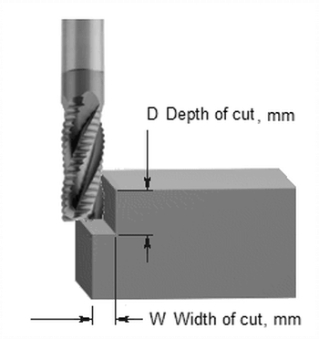
Milling operation
The expression for calculating the material removal rate during milling operation is given by:
MRR = (D x W x F ) mm3/sec
Where, D is the depth of cut (mm). W is the width of cut (mm). F is the Feed rate (mm/sec)
Example
A milling operation on a metal workpiece of width 2 mm was performed using 1 mm depth of cut, and 3 mm/rev feed rate. Determine the material removal rate for this operation
Given: depth of cut = 1 mm, feed rate = 3 mm/rev, width of workpiece = 2 mm
For milling operation,
MRR = 1 x 2 x 3 mm3/rev
MRR = 6 mm3/rev
MRR = 6 x 10⁻⁹m3/rev
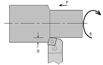
Turning operation
The expression for calculating the material removal rate during turning operation is given by:
MRR = ( D x F x S) mm3/sec
Where, D is the depth of cut (mm). F is the feed rate (mm/rev.). S is the speed of cutting (m/sec)
Example
For a turning machining on a cylindrical workpiece using 1 mm depth of cut, 3 mm/rev feed rate, and cutting speed of 4 mm/min. Determine the material removal rate for this operation
Given: depth of cut = 1 mm, feed rate = 3 mm/rev, cutting speed = 4 mm/min
For turning operation,
MRR = ( D x F x S) mm3/min
MRR = 1 x 3 x 4 = 12mm3/ min
MRR = ( 12 x 1.6667×10-11) m3/sec
MRR = 2 x 10⁻¹⁰ m3/sec
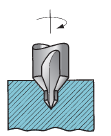
Drilling
In a drilling process, the material is cut or removed using a rotary cutting tool, leaving a circular hole in the substance.
Drill diameter (D), cutting speed (S), and feed rate (F) are all factors that affect how much material is removed during drilling. The following is the drilling material removal rate formula:
MRR = (D x F x S ) / 4 mm3/sec
Example
What is the rate of material removal for a 1 mm drilling at a feed rate of 5 mm/min and a drill speed of 12 mm/min?
Given: drill diameter = 1 mm, feed rate = 5 mm/rev, cutting/drilling speed = 12 mm/min
For drilling operation,
MRR = ( D x F x S ) / 4 mm3/sec
MRR = ( 1 x 5 x 12 ) / 4 mm3/sec
MRR = (15 x 1.6667×10-11) m3 / sec
MRR = 2.5 x 10⁻¹⁰ m3/sec
How material removal rate affects surface finish, texture, and speed of production
Cutting Conditions
To carry out a machining operation, the tool and work must move relative to one another. At a particular cutting speed, the main action is completed.
The tool must also be moved laterally across the project. The feed rate, which is substantially slower, is used in this. The depth of cut, or d, refers to how far below the initial work surface the cutting tool penetrated during the cut. The cutting conditions refer to speed, feed, and depth of cut taken as a whole. They create the three dimensions of the machining process, and for some operations (such as the majority of single-point tool operations), they can be utilised to determine the rate at which material is removed from the workpiece.
Different interpretations of the cutting conditions may be used in various machining operations. For instance, depth in a drilling operation is understood to be the depth of the drilled hole.
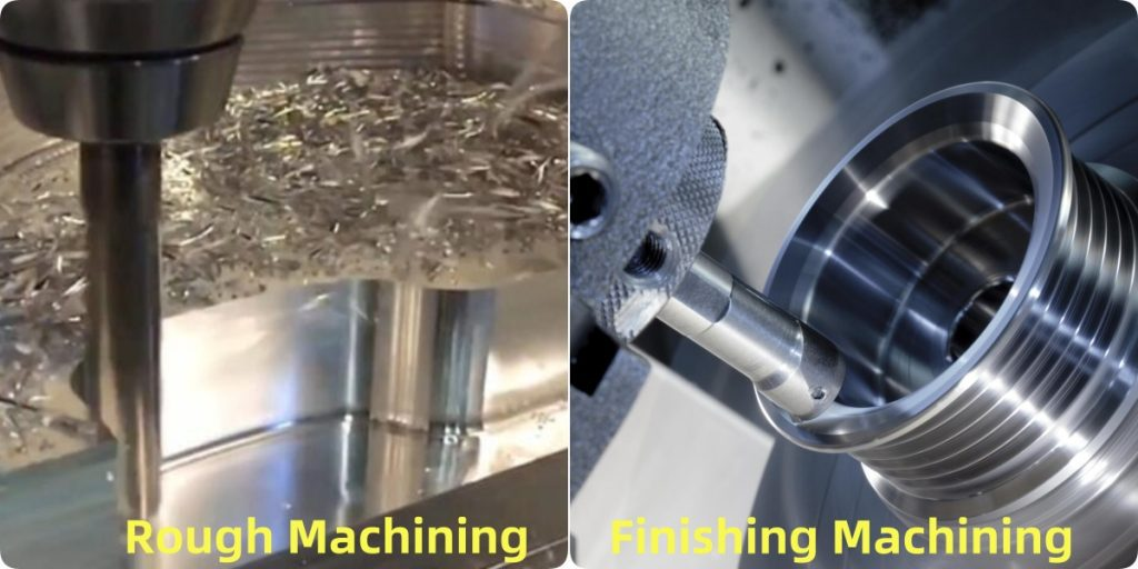
Surface finish and texture of product are achieved under two categories of machine operation, namely roughing cuts and finishing cuts.
Roughing cuts: While leaving some material on the piece for a subsequent finishing operation, roughing cuts are used to quickly remove large amounts of material from the initial work part to achieve a shape that is close to the intended form.
Finishing cuts: To complete the product and obtain the desired final dimensions, tolerances, and surface polish, finishing cuts are employed. In production machining tasks, the work typically undergoes one or more roughing cuts before one or two finishing cuts. High feeds and depths are used during roughing operations; typical feed rates range from 0.4 to 1.25 mm/rev and depth ranges from 2.5 to 20 mm.
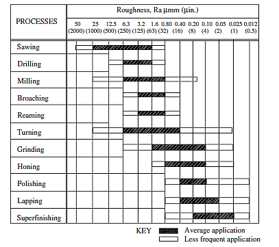
Typical machining techniques and range of rough surfaces produced.
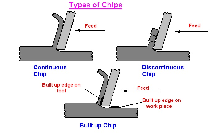
Discontinuous chip: Low cutting rates cause the chips to frequently develop into distinct segments (sometimes the segments are weakly linked) when relatively brittle materials (like cast irons) are machined. The machined surface usually acquires an uneven texture as a result. This chip type is favoured by high feed and depth of cut rates, as well as high tool-chip friction.
Continuous chip: Long continuous chips are produced when ductile work materials are cut at high speeds and relatively modest feeds and depths. This type of chip often forms with a nice surface polish. Continuous chips are more likely to form when the tool has a sharp cutting edge and there is less tool-chip friction. Long, continuous chips (such as those generated during turning) might be problematic for chip disposal and/or tangling on the tool.
Built-up edge on a continuous chip: Parts of the work material frequently stick to the rake face of the tool close to the cutting edge when machining ductile materials at low-to-medium cutting rates due to friction between tool and chip. The built-up edge (BUE) designation refers to this development. A BUE grows and forms, becomes unstable, and eventually separates off in a cyclical manner. The chip often carries away a large percentage of the detached BUE and, on occasion, even takes a portion of the tool rake face with it, shortening the life of the cutting tool. The freshly formed work surface becomes rough because portions of the detached BUE that are not transported away with the chip become embedded in it.
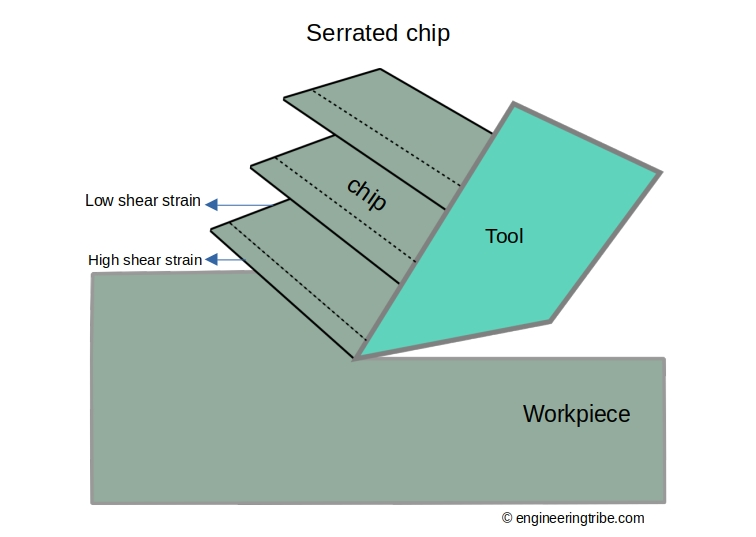
Serrated chips: These chips exhibit a saw-tooth appearance due to a cyclical chip production that alternates between high and low shear strains, making them appear semi-continuous. When harder metals like austenitic stainless steels, nickel-base superalloys, and titanium alloys are machined at faster cutting rates, this fourth form of chip is most frequently observed. However, the phenomenon also occurs when more typical work metals (such as steels) are cut quickly.
Interested in our engineering courses?
We have over 70 courses across all major engineering disciplines, including, mechanical, electrical and electronic, civil, aerospace, industrial, computer and general engineering. Visit our course catalogue for a complete list of fully accredited engineering programmes.
A small selection of short courses …
Level 6 Courses
International Graduate Diploma in Mechanical Engineering
Level 5 Courses
Higher International Diploma in Industrial Engineering
Higher International Diploma in Mechanical Engineering
Level 4 Courses
Higher International Certificate in Industrial Engineering
Higher International Certificate in Mechanical Engineering
Alternatively, you can view all our online engineering courses here.
Recent Posts
Civil Engineering Courses and Diplomas: Topics, Skills and Career Routes
Civil Engineering Courses and Diplomas: Topics, Skills and Career Routes Introduction Civil engineering is the backbone of modern society. From roads and bridges to skyscrapers and water systems, civil engineers design, build, and maintain the infrastructure that keeps the world running. If you’re considering a civil engineering course or diploma, understanding what it covers is […]
What Is a Diploma in Engineering? Courses, Levels and Career Routes Explained
What Is a Diploma in Engineering? Courses, Levels and Career Routes Explained Introduction Engineering shapes the world around us, from the buildings we live in to the technology we use every day. But for many aspiring engineers, the biggest question is not whether to pursue engineering, but how to start. Traditional university degrees are not […]
Engineering Courses: How to Choose the Right Route for Your Career
Engineering Courses: How to Choose the Right Route for Your Career Introduction Choosing an engineering course can feel like standing at the beginning of several different roads, each leading towards a different kind of future. One route may lead into mechanical systems and manufacturing. Another may lead towards aircraft, infrastructure, electronics, computing, renewable energy or […]