Fitting It All Together: The Critical Role of Limits and Fit
Introduction
In the world of mechanical engineering and precision manufacturing, the smallest dimensional discrepancies can lead to significant operational failures. Whether assembling aircraft engines, designing prosthetic limbs, or constructing consumer electronics, the need for precise, repeatable, and functional component interactions is paramount. This is where the concept of limits and fits becomes crucial.
Limits and fits define the allowable variations in the dimensions of mating parts, ensuring they function correctly together. Rather than aiming for an impossible state of perfect dimensions, engineers use a standardized system to control the degree of tightness or looseness between components. This guarantees interchangeability, reliability, and efficiency in manufacturing processes, while accounting for inevitable production tolerances.
What are limits and fits?
A fit in engineering is the space between two matching pieces. Depending on the engineering fit selected, two parts may move independently of one another in a clearance fit or together in an interference fit.
Although limits and fits are applicable to various types of mating components, their primary function is to control the diameters of mating shafts and holes for optimal performance.
In general, one of the challenges facing designers today is determining the upper and lower limits of size that are acceptable for each of the dimensions used to define shape and form and that would guarantee appropriate operation in service.
Ideally, no component can be built to an exact size. For instance, a dimension of 100.02 indicates that a part can be produced anywhere between the size constraints of 9.98 and 10.02 m.
Advantages
1. Components can be “assembled” as opposed to “fitting” them together, which calls for size adjustments and a high level of competence.
2. Defective parts can be replaced with components made to the same range of dimensions in order to repair an assembly.
3. Large volumes of parts can be manufactured, often with less of an operator skill requirement. This invariably necessitates the use of specialised equipment, tools, jigs, fixtures, and gauges; but, the overall cost of each component will be far lower than if it were manufactured separately by an experienced craftsman.
It should be noted, nevertheless, that complete interchangeability is not always required or practical, particularly when very precise size control is required for the dimensions. After going through a thorough inspection procedure that divides the parts into various groups according to size, many of the units utilised in the manufacture of motor vehicles are put together.
Consider the scenario where it was necessary to keep the clearance between a piston and a cylinder within 0.012 mm. The piston and cylinder bores would need to be finished to a tolerance of 0.006 mm in order to preserve full interchangeability, which would be challenging to maintain and unprofitable to produce.
In reality, both bores and pistons may be produced with a tolerance of 0.06 mm, and after being divided into groups for assembly, each component is gauged.
Upper and lower limits of sizes
Design professionals should make sure that the drawing clearly specifies the upper and lower size limits for each dimension.
For most engineering drawings, fully defined upper and lower tolerance limits are included
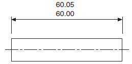
Given that the upper and lower limits are quoted and that the machine operator is not required to perform mental calculations, this may be the clearest way to indicate size restrictions on a drawing. The dimensions are given in logical form, with both limits given the same number of decimal places and the higher limit above the lower limit.
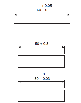
However, an alternative to the above procedure is to cite the basic size and add the tolerance limitations. It is not required to express the nominal dimension with the same precision as the limitations.
Fits can be directly obtained from those given in BS 4500, “ISO limits and fits,” and the following alternate techniques of dimensioning a hole may be used to indicate the grade of fit:
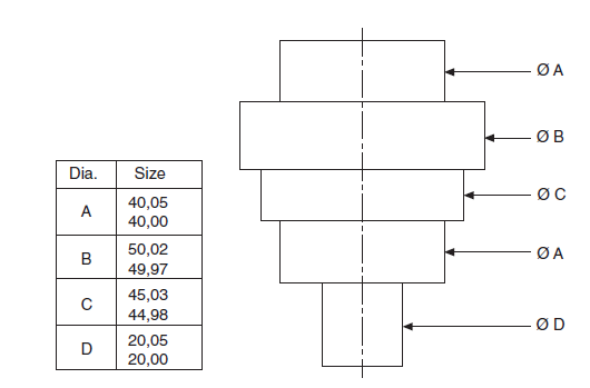
Similar to that, a shaft could have the following dimensions: Information can be provided in tabular form when there is a lot of repetition involved; an example component drawing is:
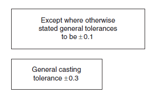
Often, tolerances just need to be general in character and span a broad range of dimensions. The drawing is given a box with a standard note.
Types of engineering fits
Three categories of engineering fits exist between two mating parts:
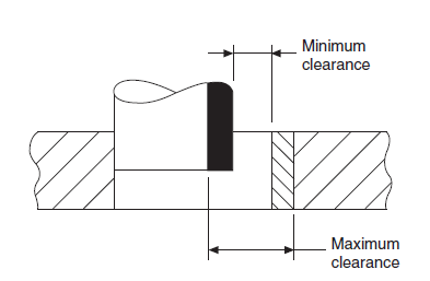
A clearance fit, in which the shaft always fits into a hole that is smaller than it, has a positive allowance.
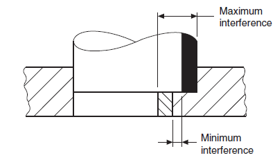
An interference fit, where the shaft is always larger than the hole it fits into, has a negative allowance.
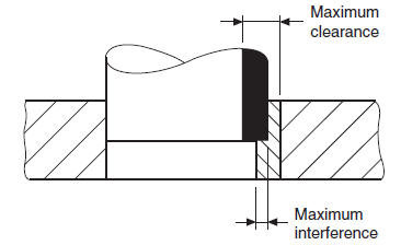
A transition fit which allows for interference or clearance fits in one group of assemblies depending on whether the shaft is larger or smaller than the hole it fits into, with positive or negative allowance.
Terms for interchangeable systems
The necessary terms using shaft and hole are explained using the diagram below
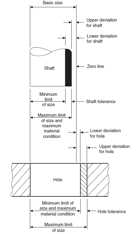
Nominal size: (25, 50, and 60 mm thread) This is the size that a component is referred to as simply for convenience.
Actual size is the size that was measured.
The basic size, which will be the same for both the male and female components of the fit, is the size to which all size limitations are fixed.
Limits of size restrictions These are the largest and smallest sizes that can be used for a given dimension.
Tolerance: The distance between the upper and lower allowed dimensions, tolerance is the maximum size variation in a dimension that is permitted.
Allowance: This relates to mating parts and is the difference between the shaft’s high and low size limits for the mating hole. An allowance could be favourable or unfavourable.
Grade: This provides information regarding the degree of tolerance; the lower the grade, the finer the tolerance.
Deviation: This is the variation between the fundamental size and the maximum, minimum, or actual size of a shaft or hole.
Maximum Material Condition (MMC): This refers to an exterior features upper bound; for instance, a shaft constructed to its high limits would have the most material possible. As an example, a component with a hole drilled to its minimal size would have the least amount of metal removed and would still be in its maximum metal state. It is also the minimum limit on an internal feature.
Least Material Condition (LMC): This is the condition that has the least quantity of material. For instance, a shaft that has been constructed to its low limits would meet this condition. It is also the highest point at which an internal feature may be formed; for instance, a hole that has been produced to its highest point would have the most material removed from it while maintaining the lowest material condition.
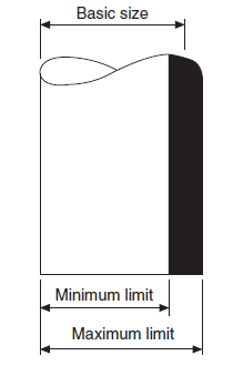
Bilateral and unilateral restrictions
An illustration of bilateral limitations, where the limits are positioned above and below the basic size, is shown below.
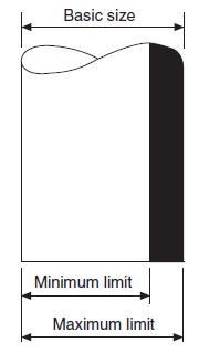
An illustration of unilateral restrictions is shown below, where the basic size’s maximum and minimum dimensions are placed side by side. Since only the size of the other gauge dimension, the NOT GO gauge size, is affected by changes in the magnitude of the tolerance, this approach is chosen since the basic size is used for the GO limit gauge.
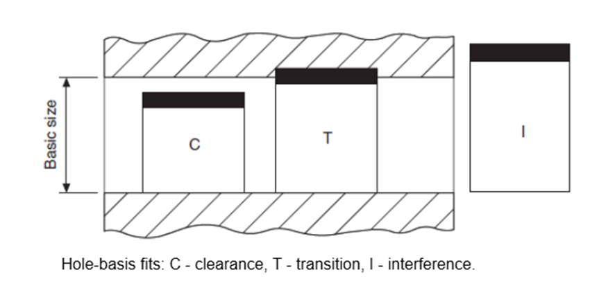
Bases of fits
Hole basis: In this approach, the shaft size varies depending on the fit type while the basic hole diameter remains constant. As a single drill or reamer size may be used to create a range of fits by simply changing the shaft limitations, this system results in increased production efficiency. By turning and grinding, the shaft can be created to the desired size with accuracy. Except in cases where large sizes may be negatively impacted by temperature, hole-base fittings are typically advised.
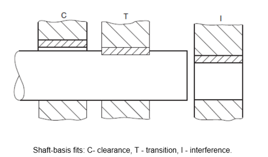
Shaft basis: In this case, the hole size is changed to provide the desired class of fit with a basic-size shaft. This approach tends to be expensive because it calls for numerous drills and reamers. However, it can be important to use it if various fittings are needed along a lengthy shaft. The current Standard on limits and fits, BS 4500, provides a range of ISO fits on the shaft basis in data sheet 4500B while this BSI data sheet 4500A provides a selection of ISO fits on the whole basis.
The hole and shaft tolerances provided by the ISO standard found in BS 4500 are many and can be used for a variety of purposes. However, it has been discovered that a small number of tolerances are sufficient for the fabrication of many common technical components. These are offered on the aforementioned data sheets. It goes without saying that having a limited set of fits results in cost savings due to the reduced need for tooling and gauging equipment.
Interested in our engineering courses?
We have over 70 courses across all major engineering disciplines, including, mechanical, electrical and electronic, civil, aerospace, industrial, computer and general engineering. Visit our course catalogue for a complete list of fully accredited engineering programmes.
A small selection of short courses …
Level 6 Courses
International Graduate Diploma in Mechanical Engineering
Level 5 Courses
Higher International Diploma in Industrial Engineering
Higher International Diploma in Mechanical Engineering
Level 4 Courses
Higher International Certificate in Industrial Engineering
Higher International Certificate in Mechanical Engineering
Alternatively, you can view all our online engineering courses here.
Recent Posts
Civil Engineering Courses and Diplomas: Topics, Skills and Career Routes
Civil Engineering Courses and Diplomas: Topics, Skills and Career Routes Introduction Civil engineering is the backbone of modern society. From roads and bridges to skyscrapers and water systems, civil engineers design, build, and maintain the infrastructure that keeps the world running. If you’re considering a civil engineering course or diploma, understanding what it covers is […]
What Is a Diploma in Engineering? Courses, Levels and Career Routes Explained
What Is a Diploma in Engineering? Courses, Levels and Career Routes Explained Introduction Engineering shapes the world around us, from the buildings we live in to the technology we use every day. But for many aspiring engineers, the biggest question is not whether to pursue engineering, but how to start. Traditional university degrees are not […]
Engineering Courses: How to Choose the Right Route for Your Career
Engineering Courses: How to Choose the Right Route for Your Career Introduction Choosing an engineering course can feel like standing at the beginning of several different roads, each leading towards a different kind of future. One route may lead into mechanical systems and manufacturing. Another may lead towards aircraft, infrastructure, electronics, computing, renewable energy or […]