An Introduction to Modelling Basic 3D Shapes in CAD Software
Introduction : What is CAD?
CAD stands for computer-aided design and it has revolutionized the way that engineers, designers, and architects work.
Computer-aided design involves creating computer models defined by geometrical parameters. These models typically appear on a computer monitor as a three-dimensional representation of a part or a group of parts, which can be readily altered by changing relevant parameters. CAD systems enable designers to view objects under a wide variety of representations and to test these objects by simulating real-world conditions.
In the past, engineering drawings had to be created by hand. Then a prototype would need to be manufactured to test the product and understand how it works. All this would need to be repeated in an iterative process to improve the part ready for final production.
This iterative process is now made substantially easier by using CAD. As an engineer, you can create a representation of the part in 3D, you can see how this part interacts and fits together with other parts, and can you even perform stress analysis to see how the part reacts under given conditions, all using computer modelling. If you need to amend the model, this can be done easily and all the associated assemblies and drawings of the part are updated automatically. This saves significant time and money by vastly speeding up that iterative process.
Take a simple example of a table, what if you need to make the leg shorter? By updating the length of one leg, then all of the four legs would automatically update and the engineering drawings would update automatically. Simple.
Introduction to AutoDesk Inventor.
This blog will use AutoDesk Inventor. This is one of the leading CAD software packages available, and widely used by industry and universities.
Basic Operating Instructions
Upon opening Autodesk Inventor, you will see the below screen (or similar). Some of the basic functions are outlined below.

- New file creation
- Recently Opened files.
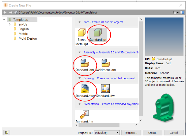
You will notice several different file types are available. We will concentrate on the below file types only:
· PART (file extension .ipt)
· ASSEMBLY (file extension .iam)
· DRAWING (file extension .dwg)
Create a Part
Open a new PART file. You should now see the below screen. Before you start to do any modelling, there are some basics that you must understand.

The main parts of the screen are:
1) The model tree – When creating a model, this will display each ‘activity’ that you complete (i.e. every sketch, surface, hole etc) so that you can quickly go back and change or edit that part of the model.
This area also displays each Plane and Axis available on the model.
2) Tool bar – Switches between different file options.
3) Tool panel – This contains all the features you will need to create your models.
4) Orientation display – This shows the orientation of which you are viewing your model, and allows you to turn and spin the model in 3D space
5) Display controls – Additional controls that allow you to pan, zoom, and spin your model etc. (although we recommend using the mouse to do all this, explained below).
Create a Cube and view it
To create any shape, firstly you must draw it in 2D, and then ‘extrude’ material to create that shape. Go ahead and click ‘Start 2D Sketch’.
You will see the below screen appear

What you can see are the 3 planes that you have available for drawing. Just like in 3D space you have a XY, XZ, and YZ plane available where X, Y, and Z are the three dimensions in space. (imagine the front wall, side wall, and floor in a room).
Now hover the mouse until any one of the planes are highlighted, and then select that plane.
The screen will change to the ‘sketch’ mode (notice the Sketch tab is highlighted on the tool bar).

Click ‘Rectangle’ on the top panel display, and drag the mouse to draw a rectangle roughly in the centre of the screen.
We now need to give this shape some sizes, so click on ‘dimension’ and pick one of the horizontal faces. You can move the mouse to position this dimension. When you click, you will be asked to enter the dimension, type ‘2’ to make the line 2 inches long.
Now click one of the vertical lines, and repeat. Make that 1” long.
It should look something like the below. (don’t worry if it’s a different size or position on the screen)

Now click ‘Finish Sketch’ and you will notice it takes you back to 3D mode and displays your rectangle. To make this a solid, you should now click ‘extrude’ and enter 1” in the pop-up box.

Congratulations, you have now created your first 3D shape! However, it may be too big or too small on the screen to see it fully.
Moving around the screen
Practise with the orientation and view controls on the right-hand side to practice zooming in and out and moving the cuboid around in 3D. You can also move around the screen using the mouse buttons.

Changing Units
One final (but very important) thing before you move onto the tutorial videos. You will have noticed that the units given are defaulted in inches. When you create any part/assembly/drawing the first thing you should do is to change the units to mm. (see below)
This can be done on the ‘Tools’ tab -> Document Settings and then ‘Units’. Change Length to ‘millimeter’ and click ‘OK’.

Creating a simple engineering drawing in CAD
We will now use Autodesk Inventor to create engineering drawings of parts and assemblies.
Part Drawings
When creating drawings of a part, it is important that there is enough information on the drawing to be able to manufacture that part. For example, we must show sufficient dimensions so that we know the size of shape of the part to be made.
In this example, the dimensions remain in Inches, don’t forget to change them to millimeters for any work on this course. This can be done under Tools>Document Settings and selecting Default Standard (ANSI-mm).

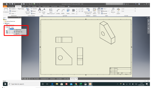
It is also important to ensure the paper size is set correctly (we recommend either A3 or A4 depending on the size of the part). This is done by right clicking on the Sheet in the model tree, and selecting Edit Sheet. You can then select the right paper size.

Title Block
Each part drawing should also contain a Title block. Autodesk will automatically create a title block for you on each drawing. You can edit the text in the title block by expanding the ANSI item on the model tree, and then right clicking on ‘Field Text’ and selecting ‘Edit Field Text’, see screenshot below. Notice how some inputs such as the Author, and Part Name are taken directly from your model.
Adding a Part and views
To pull a part into your drawing, simply select Place Views> Base. You will then get the option to find the part you want to create a drawing of, and allow you to set the scale. It is important to set the scale so that the drawing fits nicely onto the page. If it’s too small it might be hard to see the details, so try to select the smallest scale that allows the part to fit comfortably on the page. You should make sure’ Hidden Lines’ are selected under style.

Adding views
You can then simply click to place the front view (use the cube to rotate to get the correct view of the part) then add the right view, top view and isometric view.
When done, you should have something similar to the below:

Dimensions
It is important that the part drawings show sufficient dimensions for the part to be fully manufactured. Dimensions can be added under the Annotate tab>Dimension.
Once selected, Inventor will automatically create the dimension relevant to the part of the drawing that you select. For example, if you click a circle it will automatically dimension the diameter of the circle, whilst if you click a line, it will automatically dimension the length of the line.
You should add dimensions in a clear open space on the drawing sheet (some more information on dimensions can be found in the next workbook).
Notice how the dimensions are pulled directly from the 3D model, you do not need to type in the numbers! If you need to make any changes to the part, you would need to go back to the 3D model and change them there. The drawing will then automatically update with the changes you have made.
Example. Let’s add dimensions to our Base drawing:

Let’s look at it in more detail:

Some things to notice:
- The holes now have a centre mark added as per the video.
- We have only added the diameter to one hole. Notice the letters TYP 4. This standards for ‘Typical’ and means the diameter 6mm is typical for all 4 positions
We now have sufficient information to completely manufacture this base plate.
Assembly Drawing
When creating a drawing of an assembly. You should create the drawing exactly as you have done for a part.
As each part drawing contains the dimensions needed to make that specific part, there is generally no need to add any dimensions to any assembly drawing. In some cases it might be useful to show the overall height/width etc, so we will add that in these examples.
However one key piece of information that should be added onto the drawing is the Parts List.
Parts List
The part list gives the Bill of Material (BoM) needed to make the whole assembly. Notice how the part names, quantities, and item numbers are automatically generated.
You can add a description separately if needed (for example you might add the part material in this column). This can be done by right clicking on Part List in the model tree on the left hand side of the screen, and selecting ‘Edit Parts List’.
Interested in our Mechanical and Aerospace Engineering Courses?
At iLearn Engineering®, we offer a diverse range of online accredited engineering courses and qualifications to cater to different academic and career goals. Our engineering courses are available in varying credit values and levels, ranging from 40 credit Engineering Diplomas to a 360 credit International Graduate Diploma.
All Mechanical and Aerospace Engineering Courses
All Mechanical Engineering Diploma Courses are here.
All Aerospace Engineering Diploma Courses are here.
Short Courses (40 Credits)
A selection of our more popular 40 credit mechanical and aerospace engineering diplomas…
Diploma in Mechanical Engineering
Diploma in Aerospace Engineering
First Year of Undergraduate (Level 4 – 120 Credits)
Higher International Certificate in Engineering
Higher International Certificate in Mechanical Engineering
Higher International Certificate in Aerospace Engineering
First Two Years of Undergraduate (Level 5 – 240 Credits)
Higher International Diploma in Engineering
Higher International Diploma in Mechanical Engineering
Higher International Diploma in Aerospace Engineering
Degree Equivalent International Graduate Diploma (Level 6 – 360 Credits)
International Graduate Diploma in Engineering
International Graduate Diploma in Mechanical Engineering
International Graduate Diploma in Aerospace Engineering
Complete Engineering Course Catalogue (all courses)
Alternatively, you can view all our online engineering courses here.
Recent Posts
Civil Engineering Courses and Diplomas: Topics, Skills and Career Routes
Civil Engineering Courses and Diplomas: Topics, Skills and Career Routes Introduction Civil engineering is the backbone of modern society. From roads and bridges to skyscrapers and water systems, civil engineers design, build, and maintain the infrastructure that keeps the world running. If you’re considering a civil engineering course or diploma, understanding what it covers is […]
What Is a Diploma in Engineering? Courses, Levels and Career Routes Explained
What Is a Diploma in Engineering? Courses, Levels and Career Routes Explained Introduction Engineering shapes the world around us, from the buildings we live in to the technology we use every day. But for many aspiring engineers, the biggest question is not whether to pursue engineering, but how to start. Traditional university degrees are not […]
Engineering Courses: How to Choose the Right Route for Your Career
Engineering Courses: How to Choose the Right Route for Your Career Introduction Choosing an engineering course can feel like standing at the beginning of several different roads, each leading towards a different kind of future. One route may lead into mechanical systems and manufacturing. Another may lead towards aircraft, infrastructure, electronics, computing, renewable energy or […]