Decision-Making Tools Explained: Improving Engineering Project Outcomes
Introduction
When undergoing any design work there are a number of tools that can be used to provide a logical, systematic approach. This will help to set the project objectives which can then be used for idea generation, decision making, and identification of risks in the project.
There are several different tools which a design engineer can use throughout the design project to help with both identifying the project objectives, and then subsequent idea generation and decision making.
Objective Tree
The objective tree helps to define the project objectives, and provides a structured way to set them out on a page. It can be used to transform vague design statements into more specific customer requirements.
By using a diagrammatic tree structure, it also shows how each project objective links together to create the overall project. This can be very beneficial when working in teams so that everybody knows what part of the project they are working on, and how this contributes to the final design.
How do we create the objective tree?
Step 1: Prepare a list of top level design objectives
This can be done by:
– Talking with the client and asking what they want
– Ask questions such as “what is meant by that?” you should always think ‘Why?, How?, What?’
– Read through any design requirements and consider the above questions
Step 2: Grouping
You should now group any similar ideas together. One visual way to do this is using Post-it notes. Take each objective/question in turn, and consider it with the previous one. If they are a similar topic/theme, then group the cards together. If it is a different theme or idea, then create a new group. Arrange the cards on a wall with the groups of ideas in columns side-by-side.
You will end up with a matrix of cards like the below:
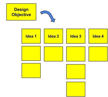
By the end of this exercise, you will have all objectives grouped together by a similar theme
Step 3: Draw the tree and expand the branches
Now that we have our list of objectives organised we can create the objective tree and start to expand on each idea/objective. To do this, we should start by creating a box with the overall project listed. The next row would then be the top requirements identified in step 2. Then you should break each idea into more detailed objectives and start to put specific details in each of the different areas.
Example. The top objective is: To design and manufacture a successful bicycle.
Step 1: Everybody in the team should write down what they consider should be the top requirements for the project. My list of considerations for a successful bike project would be:
· It must be safe to ride
· It must be fit for purpose (e.g. road bike? Mountain bike?)
· It must look good
· It must be affordable
· It must be possible to manufacture easily
Step 2: Now you would review everybody’s objectives and group together similar ones. For our example here, I will stick with the above list of top-level requirements.
Step 3: Create the tree and expand the branches:
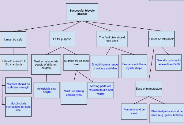
Notice how during the decision making, we decided to move ‘ease of manufacture’ to a sub-category of affordability. There are no problems moving things across and joining different categories if you decide there are links or similarities between them.
Once you have the objective tree completed, the bottom layer, i.e. any boxes that are not expanded anymore (shown in blue text), now gives you a list of specific objectives that can be used to create or support your detailed design specification.
Cause and Effect Diagram
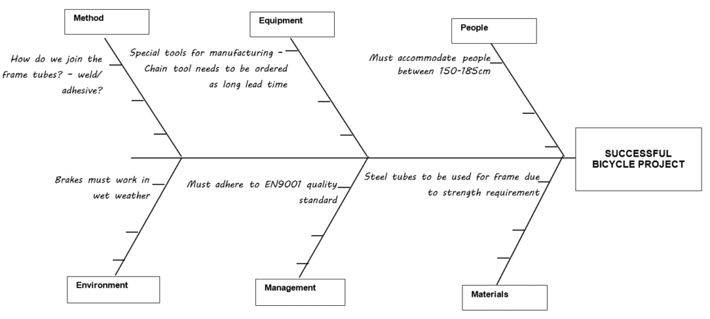
A Cause and Effect diagram (also known as a Fishbone diagram due to the shape of them, or an Ishikawa diagram after the creator of a diagram) is a simple but effective tool for brainstorming ideas during the product development phase.
Traditionally used to diagnose quality escapes or provide possible solutions to a problem, the technique can equally be as effective during product development.
A cause and effect diagram is a combination of brain-storming and a process map. You start with the output (i.e. the project goal) and think about all the possible inputs to the design using the following six categories as a framework. People, Method (or process), Equipment, Materials, Environment, Management.
For each of the six categories we should then start to ask some fundamental questions, for example:
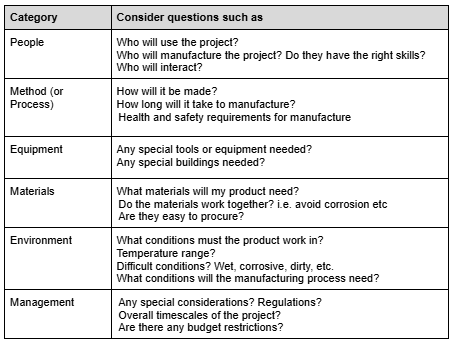
These basic questions will act as a good starting point to gather your list of design requirements for the project.
It is possible to change or remove categories to suit specific project objectives, however these six are a sufficient starting point for the majority of engineering design projects.
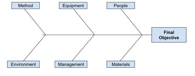
To help you to visualise the inputs, a cause-and-effect diagram arranges these six categories onto a ‘fishbone’ shape diagram like the below. The overall project goal should be at the head of the diagram. The requirements coming from each question are then added as a new point on the relevant branch.
Decision Matrix
In order to make an evaluation of different design ideas, it is important to have a set of criteria to score them against. A decision matrix arranges the criteria in a table and uses scoring to determine which of the several potential design solutions or alternatives most match the requirements.
Firstly, the criteria should be based on the design objectives. So the output to the objective tree above would be a very good starting point to use as our criteria.
The decision matrix then applies a numerical weight to each objective, and numerical scores to the performance of each design idea against those objectives.
The basic steps for creating a decision matrix are:
- List the design objectives/requirements (you can use the outputs from the objective tree as a starting point)
- Give each requirement a weighting of 1-5 of importance. Where 5 is critical to success, and 1 is a ‘nice-to-have’. This takes your judgement as an engineer as to what is important, and should be discussed with the client as much as possible. In a large organisation this would be done with a group of people to get multiple opinions.
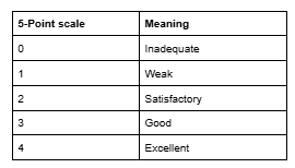
- Establish performance scores against each objective for each design idea. For this you should use a simple points scale such as the below:
4. Calculate and compare the relative scores for each design idea.
To do this, you multiply each of the requirement scores of each idea by the associated weighting for that requirement. You can then simply sum the total score for each idea.
You can then rank each idea in an ‘Order of Merit’, with 1 being the best idea. This should give you a good suggestion to which design solution best meets the original brief. If several ideas have a similar score, you may wish to discuss the selection with the client before deciding on a final design to progress through to production
Example. An example layout of a Decision Matrix for our bike is shown below:
(figures shown in red are simply examples to show how the table should be completed and scores calculated).
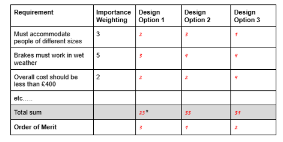
*Remember, 25 is generated from (3×2) + (5×3) + (2×2)
Conclusion
By using standard tools such as the objective tree, and the cause and effect diagram, you can start to break down and evaluate the list of requirements that you’ll need to consider through the design project. You may also have a list of outstanding questions that you’ll either need to discuss with the client, or simply find a solution for!
Once you have generated sketches and ideas of different solutions to meet these design requirements, then by using a simple decision matrix it can help you to determine which of your ideas more closely match the original objectives, and will therefore support your proposal towards the final product design.
Interested in our Mechanical and Aerospace Engineering Courses?
At iLearn Engineering®, we offer a diverse range of online accredited engineering courses and qualifications to cater to different academic and career goals. Our engineering courses are available in varying credit values and levels, ranging from 40 credit Engineering Diplomas to a 360 credit International Graduate Diploma.
All Mechanical and Aerospace Engineering Courses
All Mechanical Engineering Diploma Courses are here.
All Aerospace Engineering Diploma Courses are here.
Short Courses (40 Credits)
A selection of our more popular 40 credit mechanical and aerospace engineering diplomas…
Diploma in Mechanical Engineering
Diploma in Aerospace Engineering
First Year of Undergraduate (Level 4 – 120 Credits)
Higher International Certificate in Engineering
Higher International Certificate in Mechanical Engineering
Higher International Certificate in Aerospace Engineering
First Two Years of Undergraduate (Level 5 – 240 Credits)
Higher International Diploma in Engineering
Higher International Diploma in Mechanical Engineering
Higher International Diploma in Aerospace Engineering
Degree Equivalent International Graduate Diploma (Level 6 – 360 Credits)
International Graduate Diploma in Engineering
International Graduate Diploma in Mechanical Engineering
International Graduate Diploma in Aerospace Engineering
Complete Engineering Course Catalogue (all courses)
Alternatively, you can view all our online engineering courses here.
Recent Posts
Civil Engineering Courses and Diplomas: Topics, Skills and Career Routes
Civil Engineering Courses and Diplomas: Topics, Skills and Career Routes Introduction Civil engineering is the backbone of modern society. From roads and bridges to skyscrapers and water systems, civil engineers design, build, and maintain the infrastructure that keeps the world running. If you’re considering a civil engineering course or diploma, understanding what it covers is […]
What Is a Diploma in Engineering? Courses, Levels and Career Routes Explained
What Is a Diploma in Engineering? Courses, Levels and Career Routes Explained Introduction Engineering shapes the world around us, from the buildings we live in to the technology we use every day. But for many aspiring engineers, the biggest question is not whether to pursue engineering, but how to start. Traditional university degrees are not […]
Engineering Courses: How to Choose the Right Route for Your Career
Engineering Courses: How to Choose the Right Route for Your Career Introduction Choosing an engineering course can feel like standing at the beginning of several different roads, each leading towards a different kind of future. One route may lead into mechanical systems and manufacturing. Another may lead towards aircraft, infrastructure, electronics, computing, renewable energy or […]