Engineering Design in the Real World: Constraints and Practical Implications
Introduction :
Engineering design rarely happens in a vacuum. While creative concepts and theoretical models provide the foundation for innovation, the transition from an idea to a working solution is shaped by a wide range of real-world constraints. Engineers must constantly balance performance, cost, materials, manufacturability, safety, sustainability, and regulatory requirements, all while ensuring that the final design meets the needs of users and stakeholders.
Understanding these constraints is essential for producing feasible, reliable, and efficient engineering solutions. This blog explores the key technical and practical factors that influence engineering design, showing how engineers turn theoretical possibilities into practical, real-world outcomes. Whether you are a student, apprentice, or practising engineer, gaining insight into these limitations will strengthen your ability to develop robust and effective designs
Ergonomics
“Ergonomics is the scientific discipline concerned with the understanding of interactions among humans and other elements of a system, and the profession that applies theory, principles, data and methods to design in order to optimise human well-being and overall system performance.” International Ergonomics Association
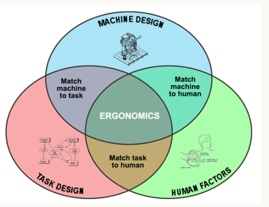
Put simply, ergonomics is the science of making sure that the things we design are suitable for human use, in terms of how they work, size, comfort, and ensuring safe use. Ergonomics is a combination of disciplines. The human factors (anthropometry and biomechanics) come together with the equipment (machine design) and job requirements (task design).
Human Factors: Dimensions, forces, movement, senses (touch, visual, audible etc)
Task Design: Management of time, ease of use, information overload, number of things to do at once.
Machine Design: Hardware to provide function and arrangement, assembly, servicing, reliability, manufacturability.
Taken from the Chartered Institute of Ergonomics and Human Factors:
“Ergonomics is a science-based discipline that brings together knowledge from other subjects such as anatomy and physiology, psychology, engineering and statistics to ensure that designs complement the strengths and abilities of people and minimise the effects of their limitations.
Rather than expecting people to adapt to a design that forces them to work in an uncomfortable, stressful or dangerous way, ergonomists and human factors specialists seek to understand how a product, workplace or system can be designed to suit the people who need to use it.
In achieving this aim, we need to understand and design for the variability represented in the population, spanning such attributes as age, size, strength, cognitive ability, prior experience, cultural expectations and goals.
You usually don’t notice good design, unless it’s exceptionally good, because it gives us no cause to. But you do notice poor design. If you’ve ever got lost in an airport with poor signage, stared helplessly at a machine with incomprehensible instructions, cut your hands on poor packaging or sighed as you had to move things around to reach something you need, you know that a lack of ergonomic design can be incredibly frustrating.
In the transport sector and in aviation in particular, the adoption of a human factors approach has changed the design of air traffic control systems, flightdecks and aircraft interiors. Human factors specialists are embedded within the teams that deliver our national air traffic services.
New sensor and communications technologies have led to advanced glass cockpits in military and civilian aircraft; ergonomics and human factors ensures that these advances are implemented in a way that enables the human pilot to remain ‘in the loop’ when controlling the aircraft, as well as taking advantage of the accurate sensing and visualisation tools provided by engineering innovations. And, as passengers, we are now helped to evacuate safely from aircraft through designs of interior lights and safety information, informed by ergonomics research.
For many years, the high-hazard industries have recognised the importance of minimising the risk from human error. The nuclear sector has led the way in understanding, measuring and improving human reliability, and it has an enviable reputation, having avoided the major accidents which have marred other industry sectors, such as the Buncefield oil depot explosion. UK nuclear regulation is seen by many as the gold-standard.
In healthcare, ergonomists and human factors professionals are working in partnership with clinicians, managers and IT specialists to ensure a safe and resilient 21st century healthcare system. Much focus has been placed on improving communications between clinicians, ensuring that teams of doctors and nurses work together to make effective decisions and reduce the likelihood of harm. In addition to this important work, many pieces of equipment that we find in a clinical setting, from ambulances, to drips that deliver life-saving drugs, have been developed and evaluated by human factors experts.”
As you can see from the experts above, ergonomics plays a part in every field of engineering from aerospace, nuclear, healthcare, and more.
Example Design
A simple example will illustrate the principles of how ergonomics can be applied in design, have a look at two pairs of pliers below
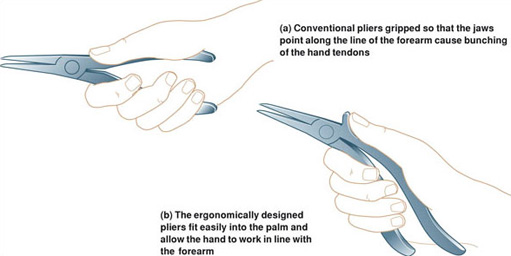
The pair at the top are a familiar conventional design, which appears to make good economic and practical sense. The tool is made in two identical parts, therefore minimising production costs, joined with a pivot. The overall form has evolved over generations from crude forebears such as blacksmiths’ tools and acquired a certain elegance and wholeness in its appearance. The design looks as if it has reached an end point in the process of evolution towards a perfect form. The pair below, on the other hand, look awkward and are made out of two very different halves. Yet trials have shown this ergonomically designed pair are more comfortable and efficient to use than their classical predecessors. The reason the conventional design is inferior is because to use it you have to bend your wrist in such a way as to cause unnecessary strain.
The ergonomic design is based on studies of the anatomy of the hand, wrist and arm, in particular how the muscles and tendons operate, and the study of how people hold and use pliers.
Anthropometry and Percentiles
Anthropometry is the measurement of human dimensions. Biomechanics includes the forces and motions. For the engineer or designer, these can define an acceptable range of values for positions, motions and forces.
Percentiles- Percentiles tell us what percentage of the human population would fit within a certain range or characteristic. If something is the 99th percentile, that means that 99% of the population would fit that measurement, meanwhile if something is 1st percentile, only 1% of people would match that characteristic.
As a design engineer, we can use anthropometric tables to find out the percentiles for many different measurements, such as height, weight, arm length, leg length etc. so that we can be sure that our design is suitable for the majority of the target market.
Let’s look at an example. If we are designing a new car for the UK market, there are many considers that must be taken for the driver’s seat such as:
- Distance to the steering wheel
- Distance to the pedals
- Force needed on the pedals
- Force needed on the steering wheel
Our target audience is adult female and male drivers, therefore we can instantly discount designing the driver’s seat to accommodate children. Instead, we would use anthropometric tables to make sure that the range of movement of the seat will accommodate everybody from the 10th percentile female driver, to the 90th percentile male driver.
Using a very simple anthropometric table below, that means we need to consider all heights between 154.1cm and 184.9cm.
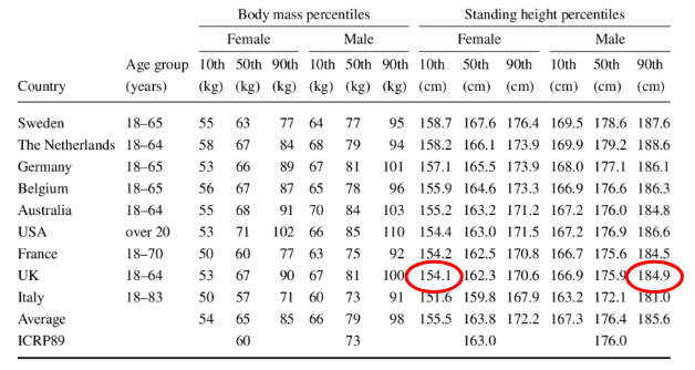
For a real car design we would need to use more detailed information on leg/arm lengths etc, and we would want to accommodate closer to the 1st and 99th percentile to cover more of the population!
In projects it is important that you use tables like these to consider the heights, weights, strengths etc of your target audience in your design.
Tolerances, Limits and fits
Tolerances
The definition of tolerances is to allow for specific variation in the size and geometry of a part.
This is important because it is impossible to manufacture to an exact size, therefore the acceptable amount of variation needs to be added to the drawing so that the manufacturer knows what is acceptable. Selecting the correct tolerances is important because allowing a large variation will affect the functionality of the part. Meanwhile, allowing too little variation will dramatically increase the manufacturing cost and lead time as special processes would be needed to make such accurate parts.
There are different ways to define a tolerance on a drawing:
Direct Tolerancing – That is defining on the drawing what is allowed against each length, angle, diameter etc. For example 10mm +/- 1mm. This would mean the feature could acceptably be 9 to 11mm.
Some different ways to present direct tolerances:
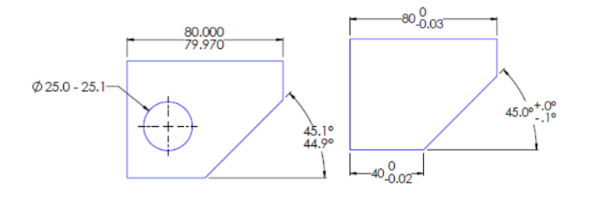
General tolerance note – This is a quick way to apply common tolerances to the whole of a drawing. E.g. “All dimensions to be held +/-0.1mm.”
Geometric Tolerances – This defines the shape of the part independent from its size. Often called “GD&T” for Geometric Dimensions and Tolerances, this uses a special system of symbols to control geometric features of a part. For example, the allowable surface finish (roughness or ‘waviness’) of a part, or the ‘roundness’ of a hole.
Fits
The fit describes how close two parts will fit together, i.e. how tight the tolerances are will affect how close parts can sit next to each other.
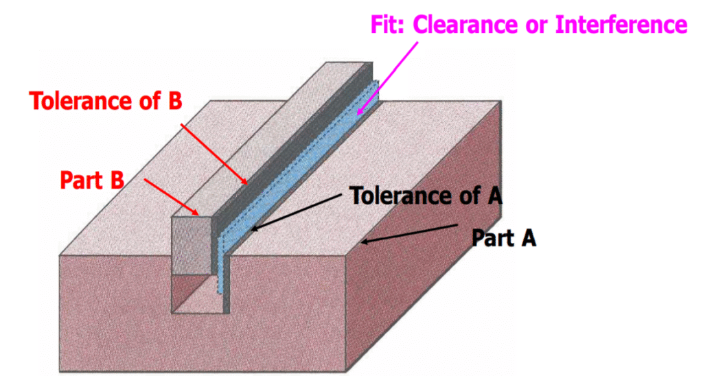
The blue shown is the ‘gap’ called clearance between the two parts.
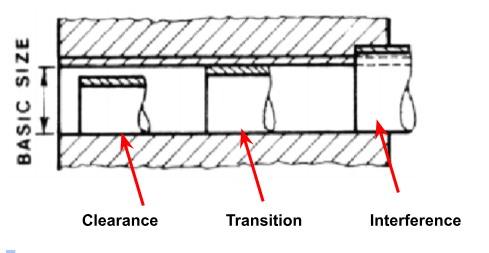
There are three types of Fit:
Clearance fit – As per the drawing above, a clearance fit means the parts will fit together with a guaranteed clearance between them. Imagine a pin with diameter 9mm +/- 0.9mm, and a hole with 10.5mm +/- 0.5mm. This is a clearance fit, because the biggest possible pin (9.9mm) will still fit in the smallest possible hole (10.0mm).
Interference Fit – Unlike a clearance fit, sometimes we might want the pin to be slightly bigger than the hole. In these situations, the pin would need to be driven/forced into the hole (perhaps by a ram or a vice) this gives a very tight fit and would be a good way of permanently joining the two parts together.
Transition Fit – A transition fit is a situation where the tolerances of the pin and the hole overlap, so that you may get a very low clearance or a very light interference. It is somewhere between a clearance and an interference fit.
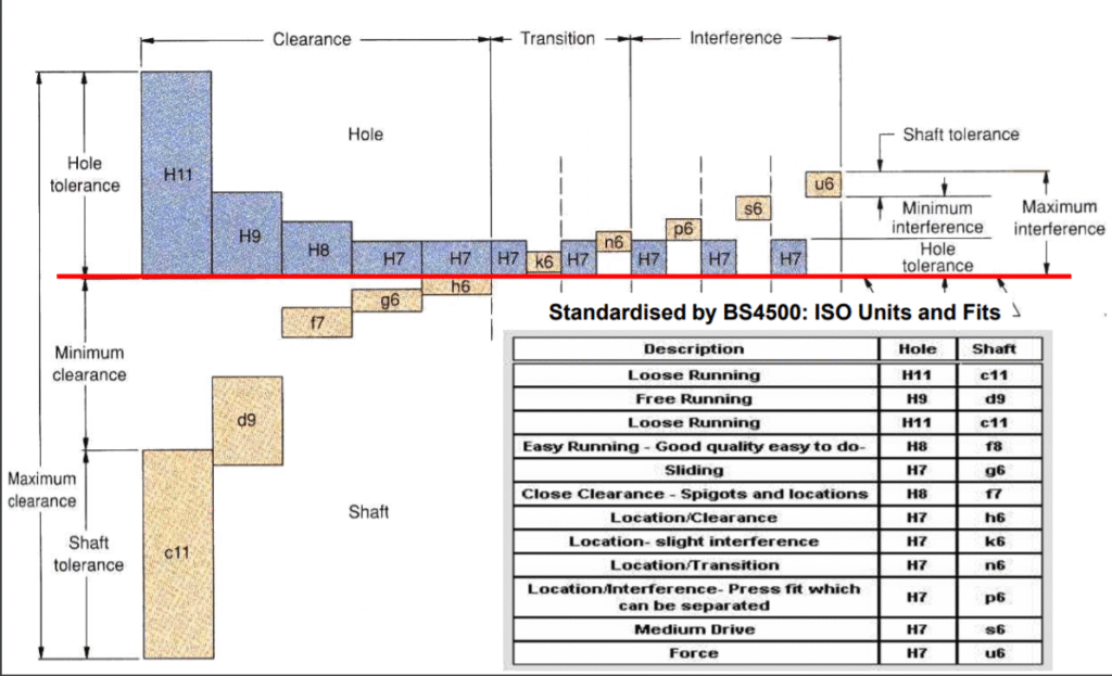
ISO Limits and Fits
The amount of clearance, transition, or interference fit required can be easily designed for by using a table for limits and fits, defined by ISO286-2. This ensures a standard approach to design and manufacturing of parts.
The table gives a series of codes made up of a letter and a number and it shows graphically the tolerances for a shaft and a hole, and what fit that would produce.
Example:
We have a shaft going through a hole which has a nominal diameter of 8mm. We want the shaft to be a tight, sliding fit. What dimensions do we need to manufacture the hole and shaft to?
The first job is to use the table to select the appropriate fit.
For a sliding fit, we will use H7-g6.
So for a hole with H7 tolerance:
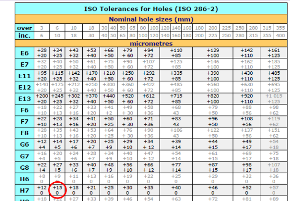
As the hole is greater than 6mm, but less than 10mm. The tolerance is +15micrometres, -0.
So the hole should be 8.000-8.015mm.
For the shaft, we selected a g6 fit, therefore:
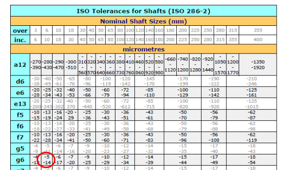
A g6 tolerance gives the lower limit as -14 micrometres, and the upper limit as -5 micrometres. Therefore the shaft needs to be:
Lower limit = 8 – 0.014 = 7.986mm
Upper limit =8 – 0.005 = 7.995mm
Therefore the shaft should be 7.986 – 7.995mm.
Interested in our Mechanical and Aerospace Engineering Courses?
At iLearn Engineering®, we offer a diverse range of online accredited engineering courses and qualifications to cater to different academic and career goals. Our engineering courses are available in varying credit values and levels, ranging from 40 credit Engineering Diplomas to a 360 credit International Graduate Diploma.
All Mechanical and Aerospace Engineering Courses
All Mechanical Engineering Diploma Courses are here.
All Aerospace Engineering Diploma Courses are here.
Short Courses (40 Credits)
A selection of our more popular 40 credit mechanical and aerospace engineering diplomas…
Diploma in Mechanical Engineering
Diploma in Aerospace Engineering
First Year of Undergraduate (Level 4 – 120 Credits)
Higher International Certificate in Engineering
Higher International Certificate in Mechanical Engineering
Higher International Certificate in Aerospace Engineering
First Two Years of Undergraduate (Level 5 – 240 Credits)
Higher International Diploma in Engineering
Higher International Diploma in Mechanical Engineering
Higher International Diploma in Aerospace Engineering
Degree Equivalent International Graduate Diploma (Level 6 – 360 Credits)
International Graduate Diploma in Engineering
International Graduate Diploma in Mechanical Engineering
International Graduate Diploma in Aerospace Engineering
Complete Engineering Course Catalogue (all courses)
Alternatively, you can view all our online engineering courses here.
Recent Posts
Civil Engineering Courses and Diplomas: Topics, Skills and Career Routes
Civil Engineering Courses and Diplomas: Topics, Skills and Career Routes Introduction Civil engineering is the backbone of modern society. From roads and bridges to skyscrapers and water systems, civil engineers design, build, and maintain the infrastructure that keeps the world running. If you’re considering a civil engineering course or diploma, understanding what it covers is […]
What Is a Diploma in Engineering? Courses, Levels and Career Routes Explained
What Is a Diploma in Engineering? Courses, Levels and Career Routes Explained Introduction Engineering shapes the world around us, from the buildings we live in to the technology we use every day. But for many aspiring engineers, the biggest question is not whether to pursue engineering, but how to start. Traditional university degrees are not […]
Engineering Courses: How to Choose the Right Route for Your Career
Engineering Courses: How to Choose the Right Route for Your Career Introduction Choosing an engineering course can feel like standing at the beginning of several different roads, each leading towards a different kind of future. One route may lead into mechanical systems and manufacturing. Another may lead towards aircraft, infrastructure, electronics, computing, renewable energy or […]