From Sketch to Solution: Your Introduction to Engineering Drawings
Introduction
Drawings are important for all engineering projects. They are a vital form of communication between engineers, designers, manufacturers etc. all working to a common language.
There are several ways of creating engineering drawing, however by far the most popular now is using CAD software to create a model of an object and transform this into a set of 2D drawing for communication and manufacture.
Design sketches
Before any 3D modelling takes place, sketches are a great way to initiate ideas and concepts. These could be from a client to a designer to describe their vision, or created by the designer to generate ideas. These do not need to take a formal method, but are simply sketches and ideas put onto paper.

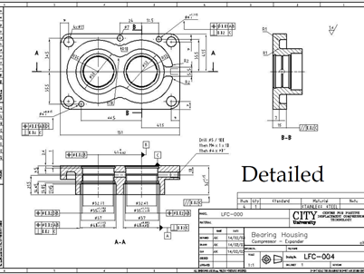
Detailed Drawings
Detail drawings are now formal 2D drawings of a physical part. They contain information such as the actual shape of the part along with key information such as dimensions, sizes, and tolerances. Engineering detail drawings follow set standards to create a common language
Assembly drawings
Assembly drawings bring together a collection of parts to form an assembly. They show how different parts fit together and interact with each other. It would typically also include the BoM or ‘Bill of Materials’, that is a list of the parts needed to make the assembly. The main assembly drawing for a project is often referred to as a General Assembly or GA.

Page Layout
There are several international standards in use around the world for creating engineering drawings. All of them follow a similar method and way of working. Let’s take a look at British Standard BS8888. This standard sets out how a page should look, and what information is required.

Let’s take a more detailed look at the ‘title block’ at the bottom.
Some critical pieces of information that should be included in the title block:
– Scale
– General tolerances
– Sheet numbers
– Date
– Sheet size
– Issue and Revision number
– Drawn by/author
– Drawing title
– Drawing method (first/third angle projection) – more on this below
You’ll also notice a strange symbol:
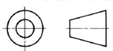
This symbol means the drawing is in Third Angle Projection. We’ll explain what this means below.
Drawing Views
To turn a 3D object into 2D drawing, you have to imagine that each face of the object is projected onto a surface.

This has created a view looking at the ‘front’ of the object.
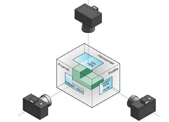
Now imagine if we do that for every face of the object like in the diagram below. We could effectively get 6 different views of the object.


Or you can think of it like a camera in different positions:
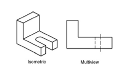
We can put these images together and we get two types of drawings, a (3D) ‘isometric view’ and the (2D) Multiviews.
First angle projection – the object is placed in the first quadrant and is positioned in front of the vertical plane and above the horizontal plane (as per below). Don’t worry too much about this as we will focus on the more commonly used third angle projection.
Third angle projection – In third angle projection, the 3D object to be projected is placed in the third quadrant and is positioned behind the vertical plane and below the horizontal plane. Unlike in first angle projection where the plane of projection is supposedly opaque, the planes are transparent in third angle projection.

A quick summary of first vs third projection is shown below:

Creating drawings
We will now only focus on third angle projection, and will create drawings using a Front view, Right side view, and Top view. (Similar to our camera example views).

When creating the drawings, you should draw the objects as you would see them from these views. However, you should imagine the object is transparent. Anything that is ‘hidden’ e.g. the hole on the shape below when seen from above is drawn using dashed lines.
Everything on the drawing should be drawn to scale and be positioned on the page so that the features line up (e.g. the green dotted lines on the image below show you that these drawings are correct
Example
Draw these two shapes from the directions given.

Image 1:

Image 2

Interested in our Mechanical and Aerospace Engineering Courses?
At iLearn Engineering®, we offer a diverse range of online accredited engineering courses and qualifications to cater to different academic and career goals. Our engineering courses are available in varying credit values and levels, ranging from 40 credit Engineering Diplomas to a 360 credit International Graduate Diploma.
All Mechanical and Aerospace Engineering Courses
All Mechanical Engineering Diploma Courses are here.
All Aerospace Engineering Diploma Courses are here.
Short Courses (40 Credits)
A selection of our more popular 40 credit mechanical and aerospace engineering diplomas…
Diploma in Mechanical Engineering
Diploma in Aerospace Engineering
First Year of Undergraduate (Level 4 – 120 Credits)
Higher International Certificate in Engineering
Higher International Certificate in Mechanical Engineering
Higher International Certificate in Aerospace Engineering
First Two Years of Undergraduate (Level 5 – 240 Credits)
Higher International Diploma in Engineering
Higher International Diploma in Mechanical Engineering
Higher International Diploma in Aerospace Engineering
Degree Equivalent International Graduate Diploma (Level 6 – 360 Credits)
International Graduate Diploma in Engineering
International Graduate Diploma in Mechanical Engineering
International Graduate Diploma in Aerospace Engineering
Complete Engineering Course Catalogue (all courses)
Alternatively, you can view all our online engineering courses here.
Recent Posts
Civil Engineering Courses and Diplomas: Topics, Skills and Career Routes
Civil Engineering Courses and Diplomas: Topics, Skills and Career Routes Introduction Civil engineering is the backbone of modern society. From roads and bridges to skyscrapers and water systems, civil engineers design, build, and maintain the infrastructure that keeps the world running. If you’re considering a civil engineering course or diploma, understanding what it covers is […]
What Is a Diploma in Engineering? Courses, Levels and Career Routes Explained
What Is a Diploma in Engineering? Courses, Levels and Career Routes Explained Introduction Engineering shapes the world around us, from the buildings we live in to the technology we use every day. But for many aspiring engineers, the biggest question is not whether to pursue engineering, but how to start. Traditional university degrees are not […]
Engineering Courses: How to Choose the Right Route for Your Career
Engineering Courses: How to Choose the Right Route for Your Career Introduction Choosing an engineering course can feel like standing at the beginning of several different roads, each leading towards a different kind of future. One route may lead into mechanical systems and manufacturing. Another may lead towards aircraft, infrastructure, electronics, computing, renewable energy or […]