

Determine the deflection of en-castre beams.
Following on from our previous article on deflection of beams with a combined load, we’re going to look at deflection in a different type of beam.
What is an en-castre beam?
En-castre beams, or fixed beams, have fixed supports at both ends. So, they don’t allow horizontal, vertical or rotational movement of that support.
The most important characteristic of this beam is that the slope and deflection are zero at both ends.
The below image shows an en-castre beam:

Encastre beams can also be built in walls, as you can see in the image below:

Advantages and Disadvantages of Encastre Beams
En-castre beams have some benefits, including:
- For the same span and load, fixed beams have lower bending moments than simply supported beams.
- Due to their support fixity, smaller deflections are encountered in fixed beams than in simply supported beams.
However, encastre beams also have some disadvantages. In encastre beams, if the condition of fixity at the ends is disturbed, for example, by settlement and rotational yield of supports, the consequence is that large bending moments will be induced in the beam to counter this effect. Moreover, in the case where there are changes in temperature, this will create large stresses in the section.
Structural Action of a Fixed Beam
When a fixed beam is subjected to loads, it bends, developing resisting moments and shears. The deflected shape of the beam is shown in this image:

Note that the slope and deflection at the ends A and B are zero, as they are restrained. The beam ‘sags’ for a part of its length in the middle and ‘hogs’ at the ends. This necessarily produces two points of inflection (contraflexure) corresponding to the change in the bending moment (BM).
Calculating Deflection of En-castre Beams
A standard data table can be used for the determination of deflection, moments and shear force in a fixed beam:
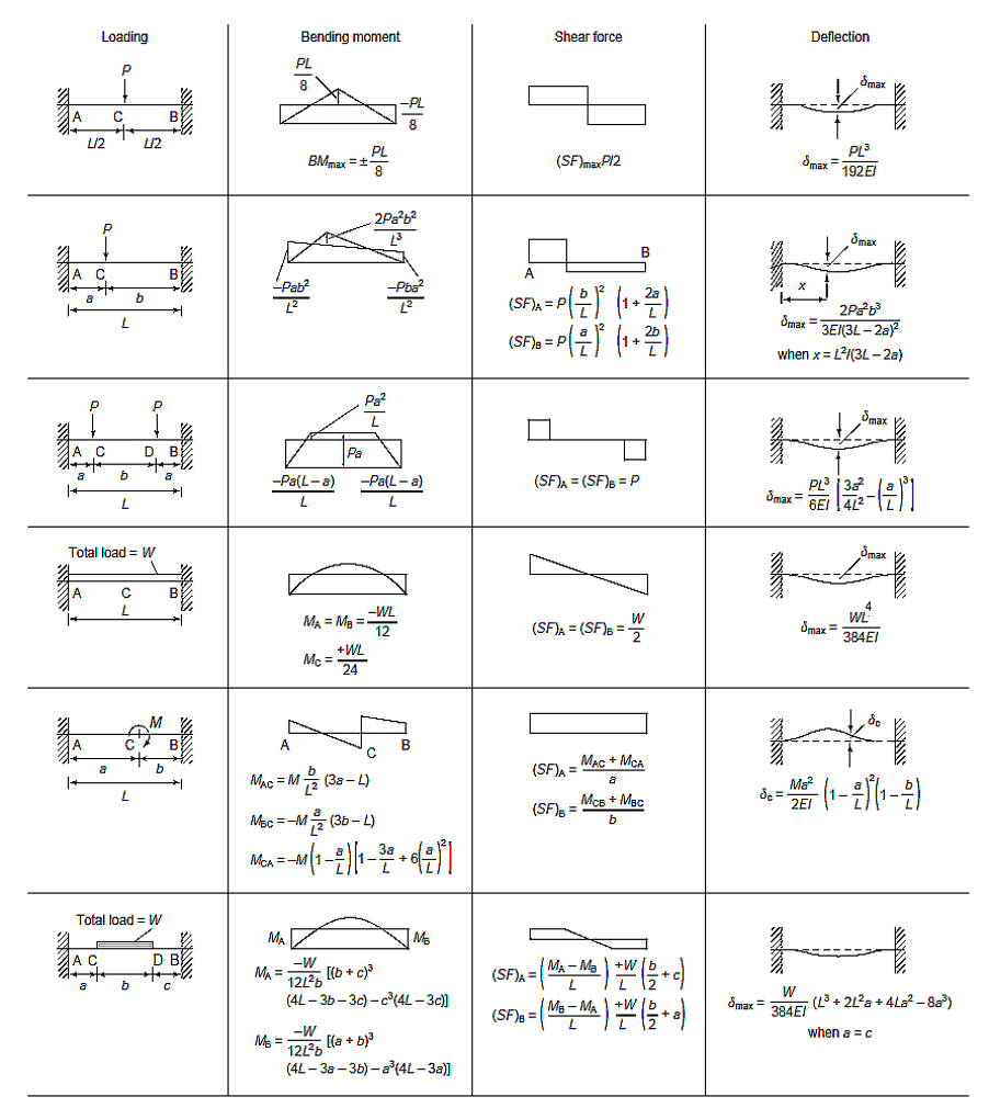
Let’s check out an example and see how we would go about calculating the deflection. A fixed beam of 6m span is loaded with point loads of 150 kN at 2m from each support. We’re going to find the maximum deflection.
Take E = 2 x 10⁸ kN/m2 and I = 8 x 108 mm4

Load = 150 kN = 150000 N
Length of beam = 6m
I = 8 × 108 mm4 = 0.0008 m4
E = 2 × 10⁸ kN/m2
For this loading arrangement case, the table gives the maximum deflection as
max = Pl36EI3a24l2-(al)3
Hence, substituting the values gives
= 1500006362 × 10110.0008322462-(26)3
= 0.03375(0.0833 – 0.037037)
max= 0.00156 m
Keep an eye out for future articles on more deflection calculations.
Interested in our courses?
Interested in civil or mechanical engineering? Find out more about all the civil engineering courses we have available by clicking here, and the mechanical engineering courses by clicking here.
Diploma in Mechanical Engineering
Diploma in Mechanical Technology
Diploma in Sustainable Construction
Diploma in Structural Engineering
Diploma in Building and Construction Engineering
Higher International Certificate in Civil Engineering
Higher International Diploma in Civil Engineering
Higher International Diploma in Mechanical Engineering
Higher International Certificate in Mechanical Engineering
Alternatively, you can view all our online engineering courses here.
Recent Posts
Why a Headwind Reduces Take-Off Distance: The Airspeed–Groundspeed Derivation
Why a Headwind Reduces Take-Off Distance: The Airspeed–Groundspeed Derivation Aeroplanes normally take off into wind because the wing must reach a required airspeed to produce lift, whereas the runway distance is travelled at groundspeed. A headwind contributes to the airspeed before the aircraft has covered any runway. It therefore reduces the groundspeed required at lift-off […]
How to Calculate Aircraft Take-Off Ground Run: A Flight Mechanics Tutorial
How to Calculate Aircraft Take-Off Ground Run: A Flight Mechanics Tutorial An aircraft does not become airborne simply because its engines are producing thrust. During the take-off ground run, thrust must overcome aerodynamic drag and rolling resistance. On a sloping runway, it must also overcome a component of the aircraft’s weight. This tutorial derives a […]
Types of Aircraft Drag Explained: Induced, Profile and Interference Drag
Types of Aircraft Drag Explained: Induced, Profile and Interference Drag An aircraft experiences several forms of aerodynamic drag at the same time. Some result from generating lift, some arise as air flows over the aircraft’s surfaces, and others are created when airflow around neighbouring components interacts. For a conventional aircraft in subsonic flight, total drag […]